17/05/2000

17/05/2000
Jerry Horn The Relationship between Harmonic Distortion and Integral Non-Linearity
Question:
I design systems which incorporate analog-to-digital converters. I often see specifications for signal-to-noise ratio and total harmonic distortion in the data sheets for these devices. If I'm mainly concerned with linearity, are these numbers of use to me?Answer:
This is not an easy question to answer. In many designs where linearity is of key concern, the answer is best left at "No, these specifications are not of use to you." However, the cases where the answer is "Yes, they are of use" are important and serve to illustrate how dynamic specifications can be of use when specifying an ADC for a given task.First, let's define a few terms. I assume by "linearity" you mean both differential non-linearity (DNL) and integral non-linearity (INL). These two specifications have different meanings but are directly related. The term linearity can also refer to INL only. The main interest here is INL, but we'll also cover DNL to some degree.
Another term is "industrial ADC." This is market segment which focuses on converters whose linearity is fully guaranteed and tested. These are generally ADCs with conversion rates of a few megahertz and below. As a comparison, audio ADCs and very high-speed ADCs (5MHz and above) may offer typical specifications for linearity, but don't guarantee the actual performance of the device.
In regards to the various specifications, differential non-linearity is a measure of how the "size" of each individual output code differs from the ideal code size. Integral non-linearity is a measure of how the converter's overall transfer function deviates from a perfectly linear (straight) transfer function.
Now, let's look at how an industrial ADC is tested. One technique to do this involves placing the ADC in a servo-loop arrangement. The goal of this setup is to provide a stable ("DC") input voltage to the ADC in order to produce a target code 50% of the time and the next higher code 50% of the time (this is called "finding the code edge"). Once this point is achieved, the voltage at the input of the ADC is measured. Testing continues with the next higher code until all codes are tested. From the array of measured voltages, it's a simple matter to calculate gain error, offset error, DNL, and INL. Other test methods also rely on a slowing changing input signal.
Note that this test method does not test the sample-and-hold performance of the ADC. Since the input voltage is stable or moving very slowly, the sample-and-hold isn't even needed. At one time, sample-and-holds were discrete devices separate from the ADC. Currently, nearly all ADCs include a sample-and-hold, so it's easy to forget that they have there own set of specifications.
Which brings us to "dynamic" specifications. These specifications include signal-to-noise ratio (SNR), signal-to-(noise and distortion) (SINAD), total harmonic distortion (THD), and spurious free dynamic range (SFDR). We're going to ignore SFDR for this discussion, but suffice it to say that it is directly related to THD. In addition SINAD is a RMS sum of both SNR and THD, so we'll ignore that specification as well.
Now, we need to look at what THD and SNR mean. In dynamic testing, the ADC digitizes a pure sine wave of a given frequency which just falls short of exercising the converter's entire transfer function (that is, the sine wave does not exceed the positive or negative limits of the converter's input range, so it does not clip). The resulting data is then transformed from the time domain into the frequency domain. Ideally, the frequency domain would show the input signal (called the "fundamental") and the converter's quantization noise (called the "noise floor") but nothing else. The spectrum for a real converter will show a number of signals or tones sticking out of the noise floor. Some of these tones are harmonically related to the input signal (twice the input signal, three times, etc.).
Signal-to-noise ratio is the power of the input signal to the total power of the noise floor excluding N harmonics of the fundamental (N is typically 3 to 9). Total harmonic distortion is the total power of the first N harmonics of the fundamental. THD can be expressed relative to the converter's full-scale input range (dBFS) or relative to the input signal (dBc, for "dB relative to the carrier"). Many manufacturer's simply list "dB" which isn't technically correct. However, if the input signal nearly covers the converter's input range, then dBFS is essentially equal to dBc.
All right, so what does all this mean? Well, without going into all the math, it can be shown that the SNR of a converter is directly related to DNL and THD is directly related to INL.
This would seem to imply that SNR and THD are not important for an industrial ADC as long as INL and DNL are guaranteed.
However, the THD of an ADC turns out to be directly related to the frequency of the input signal. Below a certain frequency, THD is only dependent on the overall INL of the converter. Above that frequency, THD is increasingly dependent on the performance of the converter's sample-and-hold. Since THD is related to INL, the INL of the converter also worsens and becomes directly related to the performance of the sample-and-hold.
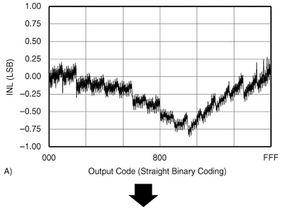
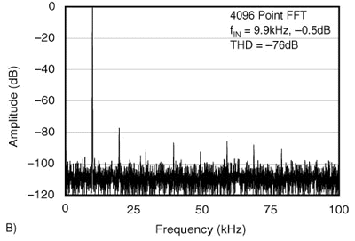
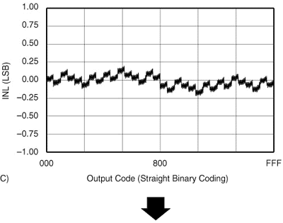
The end result is that, beyond a certain input frequency, the guaranteed INL in the data sheet has no meaning. (Note that SNR changes very slightly with input frequency and, thus, so does DNL. However, this effect can generally be ignored in most industrial ADCs.)Let's look at some examples. Graphs A and B in Figure 1 show the INL for a converter that has poor INL and also the THD for this converter. Graphs C and D show the INL for the exact same type of converter but one with much better INL. As can be seen, the THD of the second converter is considerably better than the first converter. The converters have the same sample-and-hold performance, the difference in THD is purely based on the linearity of the converter. (For the curious, the ADC shown is a 12-bit, 200kHz ADC).


~~~~~

Figure 1. Relationship between INL and THD. Now that we've established a link between THD and INL, let's look at what this means.
Turning to a different converter (a 16-bit, 40kHz ADC), Figure 2 shows a typical performance curve from the data sheet-THD vs. Input Frequency. As can be seen, the THD performance of this converter worsens considerably as input frequency is increased.
Figure 2. THD vs. Input Frequency for a 16-bit, 40kHz Sampling ADC. The INL specification for this device applies only with low frequency inputs, the very left hand side of the graph in Figure 2. As the input frequency increases, the INL worsens. This is a good time to recall the definition for INL: the deviation of the output code from the converter's ideal transfer function. So, as the frequency of the input signal increases, the output codes will deviate more and more from the desired ideal output code.
For an example, if the converter depicted in Figure 2 is being used to digitize a signal which can slew at an equivalent rate to that of a 10kHz signal, then the "THD" performance of the converter will be roughly -86dB. This figure means that the harmonic distortion is 86dB below the converter's full-scale range. Since the full-scale range of this 16-bit converter is ±32,768, then the harmonic distortion represents roughly ±1.6 LSB of error.
We have to be very careful here. If the performance of the converter at very low frequencies was also -86dB, then the INL already includes the -86dB THD number, and so we don't have to consider THD as factor. We're only interested in the how much THD has worsened. In Figure 2, the low frequency THD of the converter is roughly -101dB. This represents an INL error of ±0.3 LSB. So, the INL error has really only increased ±1.3 LSB. (Keep in mind that this calculation is a first-order approximation. Depending on the harmonics and their phase relationship, the actual errors could be somewhat different.)
A worst-case calculation would then include the INL specification of ±2 LSB (the high grade for this particular device) plus ±1.3 LSB. It would also have to include another item we haven't discussed: internal noise from the ADC. This adds an additional ±2.4 LSB of error. So, the 16-bit converter has gone from an INL of ±2 LSB to an error of ±5.7 LSB!
The reason that many designers of "industrial" systems can safely ignore THD, is that industrial processes are usually not very high speed. In addition, the performance of the sample-and-holds for industrial ADCs varies greatly. Some ADCs are not limited at all by their sample-and-holds. Others are limited to a degree.
The bottom line is to consider the maximum slew rate of your input signal. Then, look over the typical performance curves for SNR and THD in the device's data sheet. If both of these curves are flat over the frequency range of your input signal, then you can concentrate on the INL and DNL specifications of the converter. Keep in mind that you may have to convert your maximum slew rate into an equivalent frequency. Also, don't forget to include the converter's internal noise as a source of error-particularly for high resolution converters (16-bits and above).
Copyright ©1999 ChipCenter