33120A
-
Contents
- I. Introduction
- II.
Basics of the Function/Waveform Generator
(33120A)
- II.1 Functions and use of the 33120A
- II.2
Front panel Menu
- a. Selection of the termination impedance (50 Ohm or High Z)
- b. Advanced modification of a standard waveform
- II.3 Storing states
- III. IntuiLink (Wfm Editor) and user-defined arbitrary waveforms
- IV. Specifications of the 33120A
- V. Acknowledgements
- VI. References
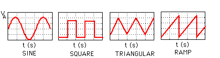
A function generator is a very versatile instrument that is extensively used in electronics, mechanics, bioengineering, physics and many other fields. It allows you to create a wide variety of synthesized electrical signals and waveforms for testing and diagnostic applications. Figure 1 shows the most common functions such as the sine, square, triangle and ramp functions.
The workstations in the laboratory are equipped with state-of-the-art function generators (33120A) which can also generate a variety of other waveforms such as a sinc (sinx/x), exponential and cardiac function. In addition, the 33120A can generate arbitrary waveforms that you create and download from memory. IntuiLink (Wfm Editor) makes it easy to create and output arbitrary waveforms.
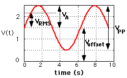
Each of the waveforms can be adjusted through the front panel controls or remotely for frequency, amplitude and DC offset voltage. As an example, lets look at a sine function described by the following equation,
-
v(t)=VAsin(2*pi*ft) +
V OFF
As with the other instruments at each workbench, the 33120A waveform generator incorporates state-of-the-art digital technologies and provides many useful functions. The generator can be remotely programmed and read by computer via a General Purpose Interface Bus (GPIB).
II. Basics of the Function Generator (33120A)
The function generator in the EE lab is based on digital signal processing (DSP) methods. A DSP is basically a beefed-up microprocessor which is specially designed for number crunching. DSPs are used in many everyday instruments ranging from a compact disc player, an electronic synthesized piano, or a voice-synthesized telephone answering message system. The DSP is able to generate complex and arbitrary functions. The principle is fairly simple and is called Direct Digital Synthesis . A simplified block diagram is shown in Figure 3.
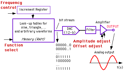
Figure 3: Block diagram of the 33120A waveform generator.
The heart of the instrument is a random-access-memory (RAM) which stores the function (e.g. sine) in digital form. This memory is addressed sequentially through an increment register. The frequency of the voltage waveform is proportional to the speed with which the RAM is addressed. The output data from the memory is a digital bit stream which is converted in the actual (analog) waveshape through a Digital-to-Analog Converter (DAC) as illustrated in Figure 3. A low pass filter at the output ensures a smooth waveform. The amplitude and offset are controlled by changing the signal gain of the amplifier at the output of the DAC.
As you know, any circuit can be represented by the Thevenin's equivalent circuit. This is shown in Figure 4a. Vgen represents the waveform (sine, pulse, etc.) and RT is the Thevenin resistance (= source resistance).
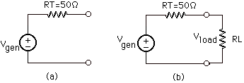
Figure 4: (a) Thevenin's equivalent circuit; (b) voltage divider between the output and load resistors.
Important is that this
source resistance of the function generator has a value of 50
Ohm . This implies that the actual output voltage
one measures over the load will vary with the load resistance
because of the voltage divider, as shown in Figure 4b.
The output amplitude is calibrated for a 50 Ohm load resistance,
which means that the voltage shown on the function generator's display
panel corresponds to the actual voltage VLOAD over the
load only when the load is equal to 50 Ohm. In other words,
the value of Vgen is double of the value displayed (or
selected) by the function generator.
If the function generator's output is measured with no load connected
(=open circuit or infinite resistance), the output voltage will be
twice the displayed amplitude. Thus, be careful when applying
the output voltage of the function generator to a circuit whose input
resistance is different from 50 Ohm.
In general, it is a good practice to measure the amplitude
of the waveform using a Digital Multimeter (DMM) or an oscilloscope
instead of relying on the function generator display reading.
II.1 Functions and Use of the 33120A Waveform Generator
The front panel of the 33120A is shown in Figure 5. There are two outputs on the right hand side of the front-panel. One is called OUTPUT and is the regular output terminal at which the specified waveform appears.. The other output terminal is called SYNC and provides a digital signal (TTL levels) that is "high" when the waveform's output is positive, relative to the zero level (or the DC offset value). The SYNC signal is "low" when the output is negative. The SYNC signal is often used as a trigger signal. Both output terminals are of the "BNC" t ype, which can be connected to a coaxial cable (i.e. a shielded cable).
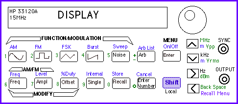
Figure 5: Front panel of the 33120A function generator/Waveform generator
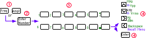
In order to set the amplitude, frequency and offset voltage of a waveform, one needs to enter numbers. Numbers can be entered in three ways:
-
(1) Use the circular knob and >
and < keys. One of the digits will be blinking on the display.
When you turn the large circular knob you can increase or decrease
the number that is blinking.
(2) Use the arrow keys <, >, up or down
(3) Use the "Enter Number" mode to enter the number
with the appropriate units shown on the right side of the panel.
First push the "ENTER NUMBER" key, followed by the number (see
green numbers next to the keys
on the front panel) and the units. At the end, push the ENTER key to
enter the number (see
Figure 6). To cancel the number mode, press SHIFT CANCEL
keys.
At power-on the function generator will output a sine wave of 1kHz and amplitude of 100mV peak-to-peak (for a 50 Ohm load resistance - see above). You can select another function or change the frequency, amplitude and offset voltage using the MODIFY keys.
b. Selection of a standard waveform
To select one of the four standard waveforms (see Figure 1), push the key with the icon of the desired wavefrom (sine, pulse, triangle, or ramp) as shown in Figure 5. After selecting the proper waveform, an annunciator will show the selected waveform on the display. Arbitrary waveforms can be selected as well. This will be explained later on (see output of arbitrary waveform ). You can now modify the amplitude, frequency (and duty cycle in case of a pulse) using the modify keys on the front panel. The following steps briefly explain how to change the frequency, amplitude and offset voltage using the MODIFY keys.
To enable the frequency mode, push the FREQ key (Figures 5 and 7) and enter the desired frequency using one of the three methods to enter numbers described above . You will see that the frequency annunciator is diplayed to indicate that you can now change the frequency. After entering the number, press one of the arrow keys to set the units (Mhz, kHz, Hz).
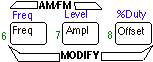
Figure 7: Using the Modify Keys to select the frequency, amplitude, offset or duty cycle
Select the Amplitude Mode by pushing the AMPL key (Figure 7). Enter the number for the amplitude in a similar way as for the frequency described above. Notice that you can express the amplitude in ( m)V peak-to-peak (VPP), in ( m )V RMS or dB using the arrow keys on the right of the front panel. As explained above, the function generator is calibrated for a 50 Ohm load which implies that the output voltage will be different from the one selected when the load resistance is different from 50 Ohm!
The minimum amplitude is 50 mVPP and the maximum 10 VPP for a 50 Ohm load (and 100mVPP and 20 VPP, respectively, for an open circuit).
The waveforms have, by default, an offset voltage of 0V, which means that the waveform will vary between a positive and negative value. If you want to offset the waveform, you will need to add an offset voltage as defined in Figure 2. To set the offset voltage, select the Offset Modify Mode and enter the number for the offset voltage. The waveform generator requires that the offset voltage obeys the following restrictions:
-
|VOFF | <= 2 x V
pp and |V OFF | + Vpp/2 <=
V max
This applies only to square waves. The default duty cycle is 50% and can be changed as follows. Select the Square Wave function by pushing the key with the square wave icon. Next, enable the duty cycle modify mode by pushing the SHIFT and %DUTY keys (see Figure 7 ). Enter the number in % and press the ENTER key.
g. Output of an arbitrary waveform
There are five built-in arbitrary waveforms stored in non-volatile memory. These include sinc, exponential rise and fall, negative ramp and a cardiac function (which simulates the heart beat of the human heart), as shown in Figure 8. In addition to these five functions, one can have four user-defined waveforms.
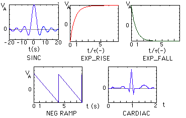
Figure 8: The five built-in arbitrary functions
To see the list of arbitrary functions, push the SHIFT and the ARB LIST keys as shown in Figure 9.
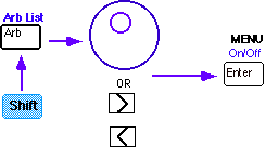
Figure 9: Selecting the Arbitrary Functions by pressing the SHIFT and ARB LIST keys
The first choice displayed will be the SINC function.
The display will show SINC for about 10 seconds. Use the >
keys or the large circular know to move across to the other
functions (EXP-RISE, EXP-FALL, NEG-RAMP, and CARDIAC). When the desired
function is displayed press the ENTER key. You can now change
the amplitude, frequency and offset voltage as described above.
Once you have selected an arbitrary waveform, this function will
be assigned to the ARB key. Every time you press the ARB key, this waveform
will be selected.
II.2 Front-panel Menu of the 33120A Waveform Generator
The waveform generator has many additional features which makes it a very useful instrument for various applications. For instance, one can modulate the waveform using amplitude or frequency (AM and FM) modulation, or can generate a Frequency Shift Keying (FSK) signal, frequency sweep, or a burst waveform. These are selected through the front-panel menu.
The menu is organized in a top down tree structure as shown in Figure 10. You move down the menu tree using the UP or DOWN keys, and move within a level using the > and < keys. The top level lets you select the main functions as shown in Figure 10. The 2nd level is the command level, and the 3rd level is the parameter level.
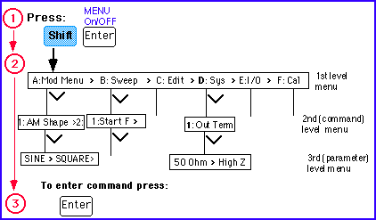
Figure 10: Menu organization
To turn the menu on press the SHIFT and MENU On/Off keys. Use the >, <, UP and DOWN keys to navigate through the menu. To enter a command press the ENTER key. For a complete list of menu functions consult the User's Guide (33120A). To recall the last menu command that was executed press the SHIFT RECALL_MENU keys. This is handy to go immediately to the right menu level.
a. Example 1: Select termination impedance: 50 Ohm or Hi Z
As an example, lets select the output termination (choice between 50 Ohm resistance or an infinite resistance High Z). The default termination resistance of the function generator is 50 Ohm as explained above. However, one can change this value to a High Z (open circuit). To select the impedance, turn the menu on by pressing the SHIFT and Menu On/Off keys. Move across the system menu using the > arrows until the following message is displayed: D : SYS MENU. Move down the system menu to the OUT TERM command (see Figure 10 ). The function generator will display 1 : OUT TERM. Move down one level and then across > until HIGH Z is displayed. Press ENTER to save this setting. Turn off the menu.
b. Example 2: Advanced modification of standard waveforms
The standard waveforms described above can be modified to create more complex ones which can be used in various applications. As an example, one can modulate the amplitude (AM) or frequency (FM) of the waveforms as shown in Figure 11 for an AM modulated sinusoid. The blue one is called the carrier frequency whose amplitude is being modulated by the lower frequency (red) sinusoid, called the modulating signal. The modulating signal does not have to be a sinusoid but can be any signal (eg. a speech signal or music, as is the case for AM radio transmission).
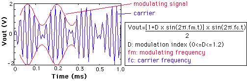
Figure 11: AM modulated sinusoid
To modulate a sinusoid follow the following steps. Select the sine function by pressing the key with the sine icon; adjust the frequency and amplitude using the modify keys. Next select AM mode by pressing the SHIFT AM keys (see Figures 5 and 12). You will notice that the AM annunciator is on.
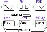
Figure 12: Selecting the AM mode
Next, use the Menu to select the shape of the modulating waveform. Press the SHIFT and RECALL_MENU buttons (this brings you directly to the AM menu). You will notice the message 1 : AM SHAPE being displayed. Move down one level until SINE is selected. Press the ENTER key to select the sine waveform. Set the modulating frequency by pressing the SHIFT FREQ key (Figure 12). The AM annunciator will flash. You can now set the frequency of the modulating signal using any of the three methods to enter numbers as described above. Next press the SHIFT LEVEL key to set the modulation depth. The modulation depth is expressed in % and has to be between 0 and 120%) (see Figure 10 for definitions).
Once you have set up your waveform such as the
AM modulated waveform above for instance, you can store them for later
use. Once a state is stored you can recall it any time. You can store
up to 3 states. To store state, press the SHIFT STORE keys and the number
(from 1 to 3) of the register in which you want to store the state. To recall
the state press the RECALL key followed by the number of the register.
III. IntuiLink (Waveform Editor) and User-defined Arbitrary Waveforms
IntuiLink Wfm Editor is a software package that allows easy communication between instruments and the PC using the GPIB interface. With IntuiLink you can draw an arbitrary waveform on the screen of the PC or use mathematical operators to create and combine waveforms. Once the waveform is created you can use IntuiLink to download the waveform to the function generator and store it in its memory. You can then recall and use this user-defined waveform as often as you like.
IV. Specifications (see also User's Manual):
- Frequency characteristics:
- Sine and square: 100µHz - 15 MHz
- Triangle and Ramp: 100µHz-100kHz
- Arbitrary
waveform:
- Length: 8 to 16,000 points
- Resolution: 12 bits
- Sample rate: 40 MSa/sec
- Non-volatile memory (arbitrary waveforms): four 16k
- Output: (into 50 Ohm):
- Amplitude: 50mVpp - 10 Vpp.
- Offset: +/- 5Vpk ac+dc
- Sourcet impedance: 50 Ohm
V. Acknowledgments
Thanks to George Hunka and Sid Deliwala for their helpful suggestions.
VI. References
1. User's Guide, HP 33120A Function Generator/Arbitrary Waveform Generator, Hewlett Packard.
2. C. F. Coombs, "Electronic Instrument Handbook," McGraw-Hill, Inc., New York, 1995.
3. "Use and Abuse of Function/Arbitrary Waveform Generator", Video, Hewlett Packard, 1996.
Created by Jan Van der Spiegel; March 6, 1997.
Updated by Jan Van der Spiegel; Jan 8, 2002
.
UNIVERSITY of PENNSYLVANIA
DEPARTMENT OF ELECTRICAL ENGINEERING