The Basics of Resistance, Voltage and Current Measurements
using the 34401A Multimeter
ObjectiveContents
The objectives of this lab are to familiarize you with the principles of test instruments for measuring DC voltage, current and resistance. You will learn the use of the digital multimeter (34401A) and the effects of the internal resistance of this meter. You will also use BenchLink ®(new: IntuiLink) to acquire and display data graphically on the PC's monitor. In addition, you will learn the meaning of the resistor color code and power rating.
One of the most important functions of the Electrical Engineering lab is to provide a working understanding of the functions and uses of instruments commonly found in all electrical laboratories. To the EE student, this knowledge is essential to efficiently conduct laboratory assignments and in developing independent design projects.
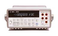
Currents and voltages are the basic circuit variables of interest. In this lab we are mainly concerned with accurately measuring resistance, DC voltage and currents using a digital multimeter (DMM). We will use the 34401A digital multimeter which is a high performance instrument capable of measuring resistance, DC and AC voltage and current, as well as frequency. The 34401A has a built-in microprocessor, memory and other electronics components that give it numerous features such as built-in math functions, recording and storing up to 512 readings, giving the maximum, minimum and average of the readings. In addition, it can be remotely programmed using the SCPI (Standard Commands for Programmable Instruments) language and read by computer via a General Purpose Interface Bus (GPIB) port.
The use of the instrument for measurement of resistance, current and
voltage is in principle very simple. Figure 1 shows the set up for resistance,
voltage and current measurements.

Figure 1: Measurement of resistance, voltage and current with a multimeter
For resistance measurements, one connects the DMM over the resistor. Notice that for voltage measurements one puts the multimeter in parallel with the circuit element so that one measures the voltage across the element. In case of a current measurement, one must put the DMM in series with the element in order to measure the current through the element. That involves breaking the circuit in order to insert the multimeter in the circuit loop. In the next section we will discuss the use of the DMM in more detail for resistance, voltage and current measurements.
Resistance measurements with the 34401A DMM
Principle of 2 wire measurement
The DMM measures a resistance by applying a known DC voltage over unknown resistance in series with a small resistance Rm . It measures the voltage over the resistance Rm as shown in Figure 2a. The DMM (remember the DMM has a built-in microprocessor) can then calculate the unknown resistance R.
Figure 2: (a) Two-wire resistance measurement; (b) four-wire measurement.
To use the DMM for resistance measurements, connect the resistor to the terminals labeled HI (V W) and LO , select the resistance measurement function by pushing the [ W] button (one of the function keys) on the front panel as shown below in Figure 3. Notice that the selection keys are annotated in black and blue. To select the function in blue, you must first select the blue SHIFT key.
Figure 3: Function buttons to select resistance, voltage, current or frequency
Measurement errors and NULLing function.
When one measures the value of a resistor one connects the resistor to the DMM input terminals using cables. If the resistor one measures is very small, it is possible that the resistance of the cables themselves are comparable or even larger than the resistance of interest. The 34401A DMM has a handy way to overcome this problem by using the NULL feature. The front panel of the DMM (see Figure 3) has a button labeled NULL. To null the wire resistance, one shorts the ends of the test wires together and then presses the NULL button. You can disable the NULL function by pushing the button again.
For really accurate measurements of small resistances, there is a clever method one can use: i.e. the 4-wire method, as shown in Figure 2b. The DMM supplies a test current through the resistor, as in the 2-wire method, but measures the voltage over the resistance with two other terminals. The two leads used for the voltage do not conduct any current, so that the lead and contact resistances do not influence the measurement . The four terminals for the 4-wire method are shown on the front panel in Figure 3.
CAUTION: When doing a resistance measurements, it is safest to disconnect all voltage sources before connecting the DMM to the circuit. Putting a large voltage over the input terminals of the DMM may damage the meter.
The multimeter automatically selects the range using the auto-ranging
feature. However, you can also manually select a fixed range (e.g. 1KOhm
or 1MOhm) using the Auto/Man button on the front panel (under
Range/Digits) buttons (Figure 4). The 'down' arrow selects the lower
range and the 'up' arrow the higher range.
Figure 4: Function, Math, Range and Menu keys
Additional features of the 34401A: average, max and min value
One often needs to take a series of data points to find the average value of the measured variable. Instead of doing this by hand, the 34401A has a built-in feature that does this for us. Also, you can ask for the maximum and minimum values during the measurement interval. To enable this feature, push the button (one of the Math buttons) on the front panel. You will see the Math annunciator lit on the front display. Also, the DMM will make short beeps indicating it is taking readings and storing the MAX, MIN, the Average value, and the total COUNT. Push the Min/Max button again to stop the readings.
To access these stored numbers, you have to turn the Menu on by pressing
the On/Off key (SHIFT <) on the
front panel (see Figure 4). Then, use the > or < keys
untill you are in the MATH (B) menu. You can now go down to the
"parameter level" of the selected MIN-MAX menu by pressing the "down"
button until you see the desired parameter menu (1:MIN_MAX) displayed.
Push once more the "down" button. Once you are in the MIN-MAX menu you
can use the > or < buttons to scroll through the
menu and read the values. The menu is organized in a top-down tree structure
with three levels, as schematically shown in Fig. 5.
Figure 5: The front panel menu organization.
The MIN-MAX feature can be used for resistance measurements as well as for voltage, current, and frequency measurements.
There are several other interesting features available. They are described in the 34401A User's Guide.
The resistance color code and power rating
Resistors are usually color coded using color banding as shown in
Figure 6. Two digits and a power 10 multiplier determine the resistance
value. The color band on the most left is the 1st significant digit, followed
by the 2nd digit and the multiplier. The fourth band is usually present
as well and indicates the tolerance of the specified resistance. The meaning
of the color code is given in Table I.
TABLE I : Resistor Color Code
| Digit | Color | Multiplier |
| silver | 0.01 | |
| gold | 0.1 | |
| 0 | black | 1 |
| 1 | brown | 10 |
| 2 | red | 100 |
| 3 | orange | 1000 |
| 4 | yellow | 10K |
| 5 | green | 100K |
| 6 | blue | 1Mega |
| 7 | violet | 10Mega |
| 8 | gray |
| 9 | white |
Figure 6: The 5% Resistor Color Code.
Power rating of resistors
In adition to the value and tolerance of a resistor, the power rating is another important characteristic. It tells how much power the resistor can dissipate before being damaged by overheating. Resistors come in different power ratings: 1/8, 1/4, 1/2, 1 and 2 Watts are typical values. Lets look at an example. Suppose you are using a 1kW resistor with a 0.25W power rating. the maximum DC voltage and current the resistor can tolerate is than Vmax=sqrt(P.R)=15.8V and Imax =sqrt(P/R)=15.6mA. Exceeding the power rating will result in poor reliability and early break-down of the circuit. The power rating depends on the physical size of the resistor, the larger the size, the larger the power rating will be.
Principle of measurement
A DC voltage is measured by using a voltage amplifier and an analog-to-digital
converter as schematically shown in Figure 7. A microprocessor further
manipulates the data before displaying the results.
Figure 7: Schematic of the DMM as a DC voltage meter.
To measure a voltage, connect the nodes over which one wants to measure the voltage between the HI and LO input terminals of the DMM (Figure 3). In order to activate the DMM for DC measurements you have to select the DC Voltage function by pushing the DC V button on the front panel (see Figure 3). The Math functions, such as Max/Min and average, can be activated in a similar fashion as was done for the resistance measurements. Also, the range can be selected manually by pushing the Man/Auto key in the Range menu.
Errors due to the internal resistance
An ideal voltmeter has an infinite input resistance so that it will
not draw any current from the circuit under testing. However, in reality,
there is always a finite input resistance Ri, as shown in
Figure 7. As a result, one has a voltage divider that will cause the
voltage V m one sees at the input of the voltmeter to be
slightly different from the actual voltage VS one wants to
measure. The 34401A has a relatively large input resistance of at least
10Mohm (depending on the selected voltage range) so that the error will
be small as long as R s << Ri.
CAUTION: Do not exceed the maximum allowable voltage input (1000V DC). Also, never apply a voltage over the current input terminal (I) of the DMM.
Principle of the measurement
An ammeter senses the current flowing through its input terminals.
The ammeter (or DMM) must be connected in series with the circuit
such the same current flows through the DMM and the test circuit. The principle
of the current measurement is quite simple. The ammeter has a small resistance
at its input terminals and measures the voltage that the test
current generates over this resistance (Figure 8). The microprocessor
then calculates the current, I=V/ri, according to Ohm's law.
Figure 8: Principle of DC current measurement.
To use the DMM as an ammeter, one connects the leads in which the current flows to the current (I) and LO terminals (see the front panel in Figure 3). To activate the ammeter, one must also select the DC I key by pushing SHIFT and DC V button as shown in Figures 3 or 4.
Error due to the non-zero input resistance
An ideal ammeter has a zero input resistance so that it does not disturb
the current under test. The small input resistance will cause a small
voltage drop which gives a small error. Fortunately, the input resistance
of the 34401A is pretty small (ri = 0.1 W
for 1 and 3 A range, and 5 W for the 10mA
and 100mA ranges) and can, in most cases, be ignored as long as RS
>> ri.
CAUTION: Do not exceed the maximum allowable current input (3A DC). Also, never apply a voltage over the current input terminal (I) of the DMM. This will cause a large current to flow through the small input resistor ri and can damage the DMM.
- DC Characteristics:
- DC Voltage range and input resistance:
- 0.1V, 1V, 10V: input resistance selectable 10M W or > 10GW
- 100V and 1000V: Rin = 10MW
- DC Current range and shunt resistance:
- 10mA, 100mA: Rshunt= 5 W
- 1A and 3A: 0.1 W
- Resistance range: 2-wire and 4-wire method
- 100 W, 1 k W , 10 kW, 100 k W , 1 MW and 100 M W
- Input protection: 1000V
- DC Voltage range and input resistance:
- AC Characteristics: true RMS
- AC Voltage: from 3 Hz to 300 kHz (for accuracy specs consult the manual)
- AC Current from 3 Hz to 5 kHz
- Frequency and Period measurement:
- Frequency range: 3 Hz - 300 kHz
- Input voltage range: 100 mV to 750 V
Benchlink is a program that allows you to program the DMM (and the other HP instruments) using graphical and menu driven commands. It gives the flexibility to make the data logging automatic and to display the results in various graphical forms on the PC.
Mr. George Hanka and Sid Deliwala for helpful suggestions and comments.
References
1. HP 34401A Multimeter, User's Guide, Hewlett Packard.
2. Electronic Instrument Handbook, 2nd edition, C.F. Coombs,
Editor, McGraw-Hill, Inc., New Your, 1995
Created by Jan Van der Spiegel, January 17, 1997;
Updated January 8, 2002 by Jan Van der Spiegel
UNIVERSITY of PENNSYLVANIA
DEPARTMENT OF ELECTRICAL ENGINEERING