Introduction
As with the other instruments at the workbench, the E3631A power supply incorporates state-of-the-art digital technologies and provides many useful functions. The supply can be remotely programmed and read by computer via a General Purpose Interface Board (GPIB).
A regulated power supply provides electrical energy which is precisely controlled. Power supplies can be of the type Constant-Voltage , Constant-Current, and the Constant-Voltage/Constant-Current sources. A Constant-Voltage (CV) supply provides a DC voltage that can be set to any desired value over a specified range. An ideal constant -voltage supply has a zero output impedance, as illustrated in Figure 1a. On the other hand, a constant-current (CC) supply gives a regulated current independent of the voltage over the load (up to the maximum allowable voltage), as shown in Figure 1b.
A more versatile power supply is the Constant-Voltage/Constant-Current supply which can be used to provide either a constant voltage or a constant current. Figure 2 illustrates the I-V characteristic of such a supply. The values Vs and Is are selected by the operator from the front panel or programmed through the GPIB interface.

Lets look at the operating modes of such a CV/CC power supply. Assume that one connects a resistive load to the power supply as shown in Figure 3. The supply has been set at a voltage V=Vs and current I=Is (see later on how to do this). The current through the resistor is then given by Ohm's law: I=V/R. As long as the current is below the maximum value Is, the voltage over the resistor will be constant and equal to Vs. The power supply operates thus in the CV mode as shown in Figure 3. However, if one decreases the resistance such that the current exceeds the maximum allowable value Is, the current will be limited to Is and the power supply operates in the CC mode. The resistance Rc =V s/I s is called the critical resistance and determines whether one operates in the CV (RL>Rc ) or CC (R L>R c) mode.
E3631A Triple Output DC Power Supply
The power supply in the lab is of the constant-voltage/constant-current type as described above. The objective of this section is to give a "hands-on feel" for adjusting the various range controls of the power supply and to give some instructions for connecting the supply to provide both positive and negative voltages.
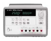
Figure 4 shows the front panel of the E3631A power supply. Italicized print indicates the switch functions. The shaded switches will not be used in this write-up. These switches control the more advanced features built into the equipment. Consult the User's Manual for more information.
The power supply has a triple output: +6V/5A, +25V/1A and -25V/1A supplies. These outputs (binding posts) are located at the lower right-hand side of the front panel of the supply (see Figure 4). In addition, the power supply has a earth ground terminal (indicated by the ^ sign) which is connected to the chassis and earth ground through a 3-wire ground receptacle.
A Simplified View of a Power Supply
Lets look at the power supply in the constant-voltage (CV) mode. A CV power supply can be considered to be a "near-ideal" battery with a very low internal resistance. As explained in the section above, its voltage will remain constant if its current rating (set to Is by the user) is not exceeded. Figure 5 illustrates this view of the power supply. Note that the ground terminal ( ^) is isolated from the battery and is connected to the chassis (or case ) ground, which is also connected to the earth ground through the 3-wire receptacle. The +25V and -25V supplies' outputs have a common output terminal (denoted by "com") which is isolated from the case or chassis ground. The positive or negative terminals of each output can be grounded or each output can be left floating with respect to the ground (must be kept within +/-240V from the chassis ground).
Figure 6 shows a few examples of how the power supply can be connected. In Figure 6a we are using both the +25V and -25V supplies and the common point has been connected to the ground. This means that one side of the two loads, Rload1 and Rload2, are connected to the chassis (and earth) ground which has a zero voltage at that node. In Figure 6b the common point between the two loads is not connected to the ground which means that this node is floating with respect to the ground. However, the voltage over the loads will be the same as in Figure 6b. Both methods of wiring can be used and usually give the same results. One can also connect the two power supplies in series as shown in Figure 6c in order to double the output voltage (to a maximum of 50 V). One can connect the + or - 25V terminal to the ground to pin down the voltage at one end.
Figure 7 shows the case where one uses the +25V, -25V and -6V power supplies in one circuit. All supplies have a common connection (the reference node) which can or cannot be connected to the ground.
Constant Voltage(CV) Operation
-
1. Connect the desired circuit to the power supply's
output terminals.
2. Turn the power supply on. After going to a start-up routine, the power supply's outputs will be disabled (the OFF annunciator is on).
3. Enable the outputs by pressing the Output On/OFF key (see Figure 9) The CV and +6V annunciators will be on to indicate that the power supply operates in the constant voltage mode and that the +6V display is selected. You can adjust the blinking digit to select the desired output voltage by turning the large knob on the top right of the front panel. The display is in the meter mode, i.e. the display shows the actual output voltage and current.
To set up the +25 V power supply, press the +25V key to select the display and adjust the +25V supply voltage. The same can be done for the -25V supply.
Figure 8: Front panel selections
The next step is to select the maximum current (limit Is ). Setting the current limit will ensure that the supply can provide enough current (and does not go into the constant current mode as explained in section " Basics of Power Supplies " above). In addition, it will protect your circuit from drawing too much current and from being damaged.
4. Set the display for limit mode by pressing the Display Limit key. You will notice the LMT annunciator blinking to indicate that the display is in the limit mode. The display shows the actual voltage and current limit values of the selected supply.
5. Press the Vol/Cur key. The second digit of the ammeter will be blinking. Adjust the knob (use the > or < buttons to switch to another digit) to set the desired current limit (make sure the LMT annunciator is still blinking).
6. When you press the Vol/Cur key again the voltage digit will be blinking. You can now adjust the voltage output.
7. To return to the meter mode press the Display Limit or let the display time-out to return automatically to the meter mode. The LMT annunciator will be off.
Constant Current (CC) Operation
The power supply can be used as a current source.
This is done in a similar way as for the CV mode.
-
1. Connect the desired circuit to the power supply
output terminals.
2. Turn the power supply on. The power supply's outputs will be disabled (the OFF annunciator is on).
3. Enable the outputs by pressing the Output On/OFF key (see Figure 8) The CV and +6V annunciators will be on to indicate that the power supply operates in the constant voltage mode and that the +6V display is selected. The display is in the meter mode, i.e. the display shows the actual output voltage and current.
To set up the +25 V power supply, press the +25V key to select the display and adjust the +25V supply voltage. Do the same for the -25V supply.
4. Set the display for limit mode by pressing the Display Limit key. You will notice the LMT annunciator blinking to indicate that the display is in the limit mode. The display shows the actual voltage and current limit values of the selected supply.
5. You will notice that the second digit of the voltmeter is blinking. Turn the large knob to set the desired voltage limit (make sure the LMT annunciator is still blinking).
6. Press the Vol/Cur key. The second digit of the ammeter will be blinking. Adjust the desired output current that the current source will supply.
7. To return to the meter mode press the Display Limit or let the display time-out to return automatically to the meter mode. The LMT annunciator will be off.
Sometimes you need to disable the voltage or current outputs. This can be done without switching off the power supply so that you do not lose the settings. To disable the outputs, press the Output On/OFF key. The OFF annunciator will go on. To enable the outputs, press Output On/OFF again.
The E3631A has several other useful features. They include tracking operation (the +25 and -25V outputs track each other); storing and recalling operating states (up to 3 different settings can be stored); system related controls, and remote interface configuration (GPIB and RS-232). Consult the User's Manual for details on these features.
- Output Ratings:
- +6V Output: 0 to +6V: 0 to 5A
- +25V Output: 0 to +25V: 0 to 1 A
- -25V Output: 0 to -25V: 0 to 1 A
- Ripple and Noise
- +6V Output: < 0.35 mV rms and <2 mV p-p; current: <2 mA rms
- +25V: < 0.35 mV rms and <2 mV p-p; current: <500 microA rms
- -25V: < 0.35 mV rms and <2 mV p-p; current: <500 microA rms
- Load Regulation:
- Voltage: <0.01% + 2mV
- Current: <0.01% + 250 microAmp
Thanks to George Hanka and Sid Deliwala for contributing to this write-up and giving helpful suggestions.
1. User's Guide, HP E3631A Triple Output DC Power
Supply, Hewlett Packard.
2. C. F. Coombs, "Electronic Instrument Handbook",
McGraw-Hill, Inc., New York, 1995.
Created by J. Van der Spiegel, Jan 23, 1997;
Updated by J. Van der Spiegel, Jan 8, 2002
UNIVERSITY of PENNSYLVANIA
DEPARTMENT OF ELECTRICAL ENGINEERING