The point(sample, memory location)- skipping nature of DDS
| DDS: Direct Digital Synthesis = point-skipping
at constant fc update(clock)-rate [ vs. traditional PPC: point-per-clock synthesis at variable clock-rate ] |
Let N data points covering one complete cycle
of a (sine) waveform (a block of N samples) be stored in the memory
(LUT: look-up table). The address pointer of LUT is a "D step
size, modulo N (mod N, overflowing)" phase ACCumulator.
D, a positive integer, is the frequency tuning word
(or simple the tuning number, or the frequency word, FCW: frequency control
word, FIW: frequency input word, FSW: frequency setting word ...)
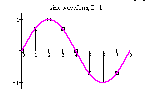
- D = 1 gives an "exact copy" of the stored waveform (the pointer steps sequentially through each address, i.e. the pointer accesses each consecutive entry in the table in the same fashion as the PPC : point-per-clock synthesis, or the sample playback synthesis).
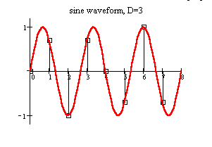
- When D > 1 , the pointer will "skip" some address, resulting in a higher frequency value:
f / fc = D / N,
D prime to N, and D < N/2.
Notes:
- If D is not prime to N and g > 1 is the gcd: greatest common divisor of D and N, then the same frequency f = (D/N).f c can be generated with less memory by replacing the tuning word of D by D/g and the numerical period of N by N/g.
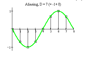
- If D > N/2 then an alias frequency appears, and there is a phase inversion ("negative frequency") in the even Nyquist zones; i.e. the phase ACC works in a "phase decrement" mode.
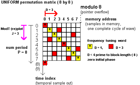
| Using a "D step size, mod N (overflowing)" phase ACCumulator as address pointer to N size LUT is equivalent with an uniform(U)-permutation (temporal rearrangement) of waveform samples within a N-block waveform. |
(1) U-permutation (temporal "scrambling" or time "shuffling") is a simple reversible mapping of sample position i into position s, withs = D.i (mod N), i = 0, 1 , ..., N-1 and D is prime to N.
Note: the tuning number D should be prime to the block length N (which is the numerical period of samples) for the mapping one to one.
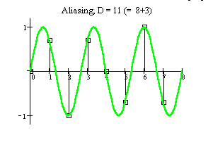
The figures illustrate this concept with a simple example (N = 8, and D = 1, D = 3). Marks in the permutation matrix are spread uniformly, hence the name.
If D > N/2 one can visually explore the aliasing phenomenon.
And, try D = 2 value - not prime to N (you get a shorter numerical period).
(2) U-permutations produce a uniform rearrangement in the DFT spectrum as well. ( U-permutation in the time-domain causes an U-permutation in the frequency-domain.)
Only the position of each component in the spectrum changes!
Note: see the References
This means that changing frequency tuning word ( D prime to a given N ! ) results in "scrambling" of the same spectral lines: the spectrum structure will differ only in the location of the components and not in the magnitude.
( See: PTperm.avi, generated from Mathcad worksheet .)(3) The inverse mapping, i.e. the sample re-ordering or ModT (re)plot (Modulo Time plot, temporal "descrambling") is performed by another (inverse) U-permutation so that J.D = 1 (mod N):
Notes: i = J.s (mod N), s = 0, 1, ..., N-1.
- The condition that J.D = 1 (mod N) results from the requirement that J.s = J . (D.i) = i, for all i. This condition is equivalent to finding an J ( and k ) such that J.D = k.N + 1, where both J and k are integers.
- See: inverse.mcd Mathcad worksheet ( for computing J ).
J is multiplicative inverse of D (and in the matrix Figure the value of J = 3 one can find graphically, too).
The inverse mapping unrolls the spectrum as well.
References:
- S. C. Kak, N. S. Jayant, "On speech encryption using waveform scrambling," The BSTJ, Vol. 56, No. 5, pp. 781-808, May-June 1977
- C. M. Rader, "Recovery of undersampling periodic
waveforms," IEEE Trans. on ASSP, vol. ASSP-25,
No. 3, June 1977
- D. L. Duttweiler, D. G. Messerschmitt, "Analysis of digitally generated sinusoids with application to A/D and D/A converter testing," IEEE Trans. on Commun., vol. COM-26, pp. 669-675, May 1978
- M. Mahoney, DSP-based testing, "Ch. 4: Coherence," IEEE Press, 1987
- S. Renaud, "Algorithm unrolls spectra," EDN
, Oct. 13, 1988