
Nov 1999
A/D converters
Once a system's performance requirements are well
understood,
an A/D converter can be selected that meets the system's
needs at an affordable cost
BY NICHOLAS GRAY
National
Semiconductor
Santa Clara, CA
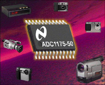
From camcorders and television cable boxes to document scanners and copy machines, high-speed A/D converters (ADCs) are critical components in today's electronic products. Because they are the interface between the analog signal and digital processing, they often determine system performance.
Resolution and speed
High-speed A/D converters can first be described in terms of two specifications:
resolution
and speed. Resolution is expressed
in bits, with an n-bit A/D converter dividing the analog input into 2n
levels, producing 2n discrete digital output codes. The resolution
needed ina A/D converter depends on the signal-to-noise ratio (SNR) and/or
the dynamic range requirements of the system.
The speed of a high-speed A/D converter
is normally expressed in millions of samples per second (Msamples/s). This
is the sample rate or the rate at which analog signals can be continuously
converted into digital form. For most applications, the sample rate should
be about three to four times the highest frequency present at the A/D converter
input.
For example, if the system SNR requirement is 45 dB, the minimum A/D converter resolution is 8 bits, as indicated in Table 1. If one or two amplifiers, or other circuitry, is in the system, an 8-bit A/D converter may not be adequate, depending on the noise performance of those other devices.
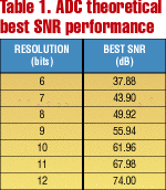
SNR is the ratio, expressed in decibels, of the rms value of the input signal to the rms value of the sum of all other spectral components below one-half the sampling frequency, not including harmonics or dc. The theoretical best SNR that can be achieved with an A/D converter is a function of the A/D converter resolution and is defined as
where n is the number of bits (resolution) of the A/D converter.
Note that this is the theoretical best SNR achievable in a "perfect" A/D converter with ideal linearity and no noise from any external source. Practical A/D converters will have SNR values that may be 2 to 10 dB or more lower than this equation would indicate because of the nonidealities of practical designs and the on-chip noise that is generated during circuit switching in the conversion process.
Actual A/D converter performance in the final circuit is often even less than this because of chosen circuit topologies, including pc-board layout. In real A/D converters, SNR degrades as signal frequency increases because some ofthe error mechanisms within the converter are frequency dependent.
Individual device SNR figures combine like resistors in parallel so that the overall system SNR is lower than the SNR of the component with the lowest SNR. For example, if the minimum system SNR should be 45 dB while sampling a 4.43-MHz signal at 20 Msamples/s, and a single amplifier with a 52-dB SNR at 4.43 MHz is ahead of the A/D converter, the required A/D converter has an SNR of 46 dB or better to achieve the overall 45-dB SNR. System SNR can be determined from the formula:
![]()
Since the theoretical best SNR of an 8-bit converter is just under 50 dB, at first glance it seems that an 8-bit, 20-Msample/s converter could do the job. A quick look at a number of 8-bit, 20-Msample/s converters, however, reveals thatmost of these converters are inadequate. This leads many designers to conclude that a higher-resolution A/D converter is needed. However, some A/D converters, such as the ADC1175 from National Semiconductor, will provide the SNR needed and it is not necessary to resort to a more expensive converter just to get therequired system SNR.
DC specifications
Speed, resolution, and SNR, however, are not everything. While resolution
indicates the number of digital output codes that an A/D converter can
produce,it does not indicate whether those codes really correspond to the
correct input voltages. Dc specifications like differential nonlinearity
(DNL), integral nonlinearity (INL), offset error,
and full-scale error describe the precision with which the output
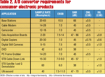
codes correspond to the input voltages (see Table 2).
DNL is the maximum error in the size of any given step in the transfer function. As the analog input voltage increases, the output code should increase by 1 LSB each time the analog input increases by VFS/2n, where VFS is the full-scale input voltage range, which is usually equal to the applied reference voltage. The code transitions should be exactly 1 LSB (VFS/2n) apart.
If a code transition occurs for an analog input voltage that is not exactly 1 LSB greater than the previous transition, there is a DNL error. Datasheet limits for DNL in high-speed A/D converters generally range from ±0.2 LSB to 1 LSB and +2 LSB.
Because the human eye is sensitive to changes in brightness, DNL is important when the A/D converter is used in display or imaging applications. If an A/D converter with too much DNL is used in a document scanner, for example, a picture with gradually changing shades of gray will appear to have distinct bands of gray. DNL is one of the most important specs for high-speed A/D converters used in imaging applications.
INL tells how far the converter transfer function can deviate from the idealstraight line between zero scale and full-scale values. INL is a summation of the DNL errors throughout the transfer function. A/D converters with high INL will have an overall curvature of the transfer function. Practical values for INL in high-speed A/D converters will range from about ±0.2 to ±4 LSB.
AC specifications
Dynamic specifications like SNR, THD (total harmonic
distortion),
SINAD or S/(N + D) (signal-to-noise and distortion),
and ENOB
(effective number of bits) indicate frequency-domain errors
that occur when the A/D converter's input is driven by a sinusoidal
waveform.
THD is the ratio, expressed in decibels, of the rms sum of the first few harmonic components of the output signal to the amplitude of the input signal present at the output. The number of harmonics specified can vary from one manufacturer to another, but six harmonics is typical.
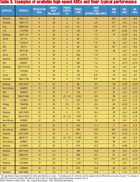
When comparing A/D converters from different manufacturers (see Table 3), check the number of harmonics they use for their THD calculations. An A/D converter that is specified with too small a number of harmonics (usually less than 5 or 6) may list an artificially optimistic value for THD in the datasheet. Excessive THD in communications applications can result in the generation of additional signals that can interfere with other communications channels.
SINAD is the ratio, expressed in decibels, of the rms value of the input signal present at the output to the rms value of all other spectral components in the output that are below half the sample rate, including harmonics but excluding dc. SINAD can be calculated from SNR and THD with either of the following relationships:
![]()
where SNR and THD are as described above.
ENOB is derived from SINAD. Because the SINAD of an ideal A/D converter
can be calculated from that A/D converter's resolution, ENOB can be calculated
from the measured SINAD of a real A/D converter.
ENOB indicates the resolution that an ideal A/D converter would have
if that ideal A/D converter had the SINAD of the real A/D converter being
considered. That is, an A/D converter that has an ENOB of 7.0 has the same
SINAD as a perfect A/D converter with 7.0 bits of resolution. ENOB can
be expressed in fractional bits:
where SINAD is expressed in decibels and ENOB in bits.
The ideal 8-bit A/D converter with absolutely no distortion and
no noise other than quantizing noise will have an ENOB of 8. However, a
real
A/D
converter will have errors that make its measured SINAD less than the ideal
value.
For example, an A/D converter with a SINAD of 45.4 dB will have an
ENOB of 7.25 bits and will have the same SINAD as a perfect 7.25-bit A/D
converter.
An A/D converter's ENOB specification in a datasheet should be determined from SINAD and not from SNR, as some manufacturers do. ENOB should be calculated from SNR only when THD is 12 to 15 dB better than SNR. Also, pay attention to the input signal frequency at which ENOB is specified. ENOB tends to degrade as frequency increases.
Note that A/D converters with similar part numbers from different manufacturers - while they may have an identical pin configuration - may not perform similarly. A/D converters cannot always be properly selected simply by reading and comparing datasheets from various manufacturers. They should also be evaluated in the laboratory.
National Semiconductor and many other manufacturers provide A/D converter evaluation boards that allow the design engineer to evaluate the dynamic performance of their converters. National Semiconductor's evaluation boards come with software that allows the designer to more easily evaluate the dynamic performance of A/D converters either with or without the aid of a computer.
Choosing the wrong A/D converter may make it difficult or impossible to meet system requirements without excessive cost. Therefore it is important to choose an A/D converter with performance consistent with the needs of the system.