04/03/2000
A Basic Guide to the AC Specifications of ADCs,
Part 1
By Jerry Horn
Question:
It's always good to go over the basics from time-to-time. In
this column, I discuss the "AC" specifications associated with analog-to-digital
converters. Such specifications include signal-to-noise ratio, total harmonic
distortion, signal-to-(noise plus distortion), and spurious-free dynamic
range. If you need to know what the numbers mean, how to interpret
them,
how
to measure them yourself, or are just curious about the specifications
in general, read on.
Answer:
Most ADC specifications can be broken into two general categories: DC and AC. These terms can be confusing because they don't really have anything to do with direct current or alternating current. Instead, they refer to the method that is used to measure the performance of the ADC.
The "DC" performance of an ADC is typically measured with a stable,
low-noise voltage source. The specifications in this category include offset
error, gain error, integral non-linearity (INL), and
differential non-linearity (DNL).
"AC" performance is measured with the use of one or more sinewave
generators. The specifications in this category include signal-to-noise
ratio (SNR), total harmonic distortion (THD), signal-to-(noise
plus distortion) (SINAD), spurious-free dynamic range (SFDR),
and intermodulation distortion (IMD).
Increasingly, AC specifications also include multi-tone power ratio
and the more general noise-power ratio (these won't be covered
here).
Basic Test Requirements for Measuring AC Performance
Measuring the AC performance of an ADC is simple (in theory):
provide one sinewave (or multiple sinewaves) to the ADC, make sure that
the signal (or the sum of the signals) exercises the ADC's full-scale input
range without clipping, perform continuous conversions on the input signal,
collect the conversion results, perform a discrete Fourier Transform (DFT)
on the data set, and calculate the ADC's performance.
Of course, the reality of AC testing is a different matter, and there are a number of compromises that are made in order to perform AC measurements. Some of these compromises are minor and create few problems, while others are more significant.
First, the Fourier Transform can be a problem for a several reasons: a general purpose discrete Fourier Transform algorithm can be computationally demanding and the data set must be "windowed" in order to provide useful results. Rather than use a general purpose discrete Fourier Transform, a specialized form know as the Fast Fourier Transform (FFT) is used. The FFT algorithm requires that the number of conversion results collected from the ADC be a power of 2: 2, 4, 8, 16, 32 ,64, etc. In order to produce repeatable AC measurements, larger data sets are used-typically in the range of 1,024 to 8,192.
Windowing of the data set presents a rather significant problem. Basically, the DFT and FFT algorithms assume that the data set represents a repetitive waveform. The two ends of the data set must fit together. (Specifically, the very first data point in the data set must be the same number that would have appeared after the very last data point.)
Assuming no particular relationship between the conversion rate and
the frequency of the input signal to the ADC, the last result in the data
set is unlikely to align properly with the first. Thus, the data must be
forced into this state through the use of a window function which tapers
the ends to zero. Unfortunately, this changes the results produced by the
FFT and these changes must be taken into account. Another problem is that
the AC numbers are less repeatable. The reason is that some of the performance
"information" collected from the ADC has been lost due to the window. This
can be corrected by collecting a much larger data set. However, it will
then take more time to process the data.
(A brief side note: Bob Masta has a number of columns on the
Fourier Transform and windowing in his archive section. The first article
in the series is: Gut-Level
Fourier Transforms: Everything You Need, You Got in High School.)
The end result of the "window problem" is that most ADC manufacturers test with "coherent" input signals. By carefully choosing the input frequency (and/or conversion rate), each data set will be repetitive with the next. Thus, no window function is required.
For coherent testing, the following mathematical relationship must be met:
- Lowest Coherent Frequency = Conversion Rate ÷ Sample Size
- Test Frequency = M × Lowest Coherent Frequency (where M is an integer)
Coherent testing is done with signal generators that can be locked to a common reference signal (typically 1MHz, 5MHz, or 10MHz) and whose frequency can be set very precisely. The locking and precision are critical in order to keep the input signal aligned with the conversion signal. Without going into the equations, you can figure out how closely the two frequencies must match by assuming that the input signal cannot be off by more than ½ of a least significant bit (LSB) by the end of the data set.
I've heard claims that coherent testing is "cheating" because it isn't very likely that the input frequencies to an ADC will be coherent with the conversion rate in the "real world." There are also concerns that coherent testing may only test a few spots on the converter's transfer function rather than the entire transfer function.
I don't buy the first claim at all. I have personally tested hundreds of ADCs with and without windowing. I've never seen a case where coherent testing yielded numbers better than non-coherent testing. In each case, coherent testing provided more repeatable numbers, but not better numbers.
The second concern is very real. Because of the mathematical relationship between the conversion rate and the input frequency (or frequencies), it's possible for the input signal to keep "hitting" the same spots in the converter's transfer function over and over. The solution is to require that M be, at the very least, an odd number and that it should, ideally, be a prime number. In both cases, M should not be one (which generally is not very useful anyway).
Another problem is the suitability of the sine generator. The AC source must have lower noise and distortion than the converter being tested. For a 16-bit converter, the signal-to-noise ratio of the source must generally be 100dB or better, while total harmonic distortion (first few harmonics) must be less than -100dB. For high resolution converters, such as 20-bit or 24-bit delta-sigma audio ADCs, finding a suitable sine source can prove to be impossible.
Even for 12-bit converters, finding a suitable generator can be difficult or impossible. The newest 12-bit ADCs on the market support conversion rates greater than 100MHz. AC testing for these converters will be done with input frequencies up to 200MHz. The AC source should have SNR of greater than 80dB and THD of less than -80dB.
The solution to this problem is very simple, but is difficult to implement: filter the generator's output with a lowpass or bandpass filter. The reason that this proves difficult in practice is that filters can be nonlinear. So, while a filter might remove distortion, it can also add distortion. As a general rule, active filters are not used to filter the AC source, so the filter is usually a passive design made up of capacitors and inductors. Capacitors can be nonlinear (see Dielectric Absorption and Distortion for more information), but the main culprit is usually the inductors.
The generator or circuit that provides the digital signal to the ADC for starting the conversion process can also be a source of problems. Remember that the AC source and the "convert command" generator must be locked together, so the generator must provide this feature. In many cases, the convert command generator is actually a sine generator and its output is converted to a digital TTL, CMOS, or ECL level signal with a fairly simple "sine-to-digital" converter.
The convert command signal must have very little jitter from sample-to-sample. Keep in mind that the ADC's sample-and-hold must grab the AC input signal very precisely. If this point changes in time from conversion to conversion, then sample-and-hold will capture the wrong portion of the input signal, corrupting the AC measurements. The amount of jitter that is acceptable will depend mostly on the frequency of the input signal and the resolution of the ADC. Note that long term changes in the conversion time are acceptable as long as the frequency of the command generator and AC source drift together (in other words, if their common reference frequency changes, then there will not be a problem as long as both generators can track the change).
AC Specifications
To quickly review, measuring the AC performance of an ADC requires:
- A low-noise, low-distortion, lockable sine source or sources (with filter(s), if needed)
- A low jitter, lockable convert command generator (or system)
- A means of capturing the digital results from the ADC (at least 1024 conversions)
- Software to process the ADC's results and display the AC performance
Generally, the phase data is not of interest, but there are very special cases where it can be useful (I will not cover those here).
The magnitude data provides the necessary numbers to compute the AC specifications. The end result is displayed in a 20 × log(magnitude) format so that the FFT result can be viewed (see Figure 1).
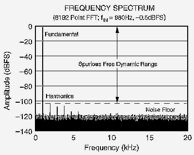
Figure 1. Frequency Spectrum of a 16-bit, 40kHz ADC Digitizing a 980Hz Input Signal.
It should be noted that Figure 1 is sometimes called an FFT, as in "Let me see that FFT." Technically, this usage is incorrect. Figure 1 is actually the frequency spectrum of the ADC's discrete time domain output which has been arrived at with the use of a Fast Fourier Transform algorithm. There are other ways that the frequency spectrum could have been computed. However, "FFT" has slipped into common usage as meaning the actual frequency spectrum itself.
Figure 1 defines the key terminology that is needed in order to describe the AC specifications. The fundamental represents the AC input signal. Since the testing is coherent (no window function has been applied to the data), the fundamental is contained in the center of exactly one "bin" of the FFT. At twice the frequency of the input signal lies the first harmonic of the fundamental. If the test setup is good, then the power in the harmonic bin is due only to the ADC and not the AC source. At three times, the input frequency is the second harmonic of the fundamental.
There can be a lot of confusion in regards to naming the harmonics. Obviously, the first harmonic of the fundamental should be called the "first harmonic." Unfortunately, there are other considerations in naming the harmonics. For example, if the harmonic number is referred to as N times the fundamental frequency, then the first harmonic will actually be called the second harmonic (meaning 2 times the fundamental). Then, the first harmonic is the fundamental itself. This has the added benefit in that harmonic "0" is actually the "DC" bin (0 times the fundamental frequency). In some cases, it's desirable to know the power in the DC bin. Thus, software can treat the various "harmonics" in a similar way. On the other hand, a problem with this approach occurs when specifying THD-that will be covered shortly in part two.
The convention adopted here is that the harmonic number refers to N times the fundamental frequency. So, the first (leftmost) of the three harmonics shown in Figure 1 is 2, the second is 3, and the third is 4.
The noise floor of the FFT represents the inherent noise in the ADC as well as the quantization noise of the analog-to-digital conversion process (which replaces an infinitely variable analog input with a discrete digital output). The level of the noise depends on the SNR of the ADC as well as the number of points in the FFT. The overall power doesn't change, but more bins in the FFT result means that the same power is divided up among them, so the noise floor drops. This will be discussed in detail in part two of this series.
The spurious-free dynamic range of the ADC is the range between the fundamental power level and the power in the largest bin of the FFT which is not the DC bin. In some special signal processing applications, harmonic distortion is not a concern, and spurious-free dynamic range is defined as the difference between the fundamental and the highest bin which is not the DC bin or a harmonic bin.
Looking at Figure 1, we have the following definitions for the various AC specifications:
SNR Fundamental power divided by the power of all the bins other than the DC, fundamental, and first N harmonic binsEach of these calculations is a power calculation: the result is the square-root(SQRT) of the sum of squares of the power in the defined bins: result = SQRT(b² + c² + d² + ...). Keep in mind that this is not an RMS calculation, the results are total power not average power.THD Power of the first N harmonic bins (usually expressed relative to some reference power)
SINAD Fundamental power divided by the power of all the bins in the FFT other than the DC and fundamental bins (SINAD can also be computed as SQRT(SNR²+THD²))
SFDR Difference between fundamental bin and highest bin that is not DC or fundamental (or, sometimes, not first N harmonic bin)
Units
The units for AC specifications are given in most ADC datasheets as
"dB." Unfortunately, the numbers and units are sometimes not consistent.
SNR is a simple ratio of two powers, so its unit should be dB. However, THD is simply a straightforward power calculation, so its unit could be expressed in watts, but that would imply a certain load value. Instead, THD is specified relative to some total power, making the THD calculation a ratio similar to SNR.
Herein lies the main problem - defining a value that will serve as a reference for THD. The simplest reference level is the full-scale range of the ADC (in Figure 1, full-scale is at the top of the graph). Referencing THD to this level and then computing a log of the result provides a number whose units are "dBFS" (decibels relative to full-scale). This has an interesting side effect: if the power in the fundamental is lowered, the THD number generally gets better because THD is not relative to the input signal, but relative to converter's full-scale range (which is constant). Harmonic distortion in most ADCs becomes much lower (better) when the input signal is lowered and/or has a slower slew rate.
It is very tempting to express not only THD in units of dBFS, but also SNR, SINAD, and SFDR. As can expected, this does occur. In nearly all cases, the text in the units column will still say "dB."
Generally, the "abuse" is fairly small. For example, a 16-bit ADC might provide 88.2 dB of SNR with an input of -0.5 dBFS. However, the typical SNR shown in the datasheet will be "89 dB" (88.2 + 0.5 = 88.7 or approximately 89). To be correct, the specification should read "89 dBFS."
One-half to one dB of error is not too bad. However, I have seen extreme cases where the input amplitude was -6 dBFS and the AC specifications were still given in units of "dB." This can make the SNR appear to be somewhat better and can make THD much better that it otherwise would be if specified correctly.
A great deal more information about AC specifications and AC testing will be presented in Part 2.
Copyright ©1999-2000 ChipCenter