04/28/2000
A Basic Guide to the AC Specifications of ADCs,
Part 3
By Jerry Horn
It's always good to go over the basics from time to time. In this column, I discuss the "AC" specifications associated with analog-to-digital converters (ADCs). Such specifications include signal-to-noise ratio (SNR), total harmonic distortion, signal-to-(noise plus distortion), and spurious-free dynamic range. If you need to know what the numbers mean, how to interpret them, how to measure them yourself, or are just curious about the specifications in general, read on.
This is Part 3 of a series concerning the AC specifications of
ADCs. Part 1 looked at the basic test requirements
for measuring AC performance, and Part 2 examined
FFT in some detail.
Figure 1 from Part 1 is referenced several times in the following
text, so Figure 1 has been reproduced here for reference purposes.
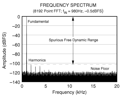
Figure 1 - Frequency Spectrum of a 16-bit, 40 kHz ADC Digitizing
a 980 Hz Input Signal
Examples
In all of my columns, I attempt to reduce the number
of graphic images to the bare minimum. I believe this improves the readability
of the material and reduces download time for those with lower speed Internet
connections. However, for this column, I have included a rather large number
of graphic images. My goal is to provide concrete examples of many of the
items I have discussed in this particular series of columns as well as
past columns. My apologies to those of you with lower speed connections,
I hope the wait is worthwhile.
The examples that follow focus on one analog-to-digital converter (ADC): the ADS8320. This is a 16-bit, 100 kHz ADC manufactured by Burr-Brown. As was stated in the columns The ADS8320: A 16-bit, 8-pin, low power SAR ADC - Part 1 and Part 2, this device is very handy for use in various situationss concerning ADCs.
In some cases, the ADS8320 will be "short-cycled" after the twelfth bit decision has been made (the conversion process will be stopped). For more information about short cycling, see Benefits of Short Cycling.
Also note that all AC results are relative to full scale (dBFS) and not to the input level (dB and dBc). This makes it easier to compare the numbers from different FFTs. However, the numbers should normally be in either dB or dBc (dB relative to the carrier).
Ideal 12-bit Performance
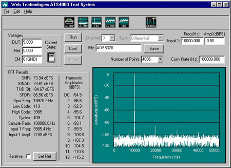
Figure 2 - The ADS8320 as an "Ideal" 12-bit Converter
Figure 2 shows the performance of the ADS8320 when short-cycled to produce a 12-bit result. When used in this manner, the ADS8320 approximates an ideal 12-bit converter. The signal-to-noise ratio (SNR) for such a converter should be 6.02 * 12 + 1.76 or 74 dB. As shown in Figure 2, the SNR is only slightly less than perfect at 73.94 dBFS.
Limiting Full-Scale Range to Improve THD
Short-cycling the ADS8320 produces a 12-bit converter with excellent
differential nonlinearity (DNL) and good integral nonlinearity (INL). However,
the INL still contributes some harmonic distortion. By limiting the full-scale
range of the converter to 80% of normal, the INL ends up being more
linear over the shorter span. This improves total harmonic distortion
(THD) as shown in Figure 3. The cost is a worsening of SNR by 2
dB, but an improvement in THD by 2 dB. (The AC results shown in Figure
3 still reference 0 dBFS, but the actual input range of this "limited"
converter would be 2 dB lower, so 2 dB must be subtracted from the numbers
shown).
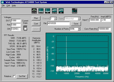
Figure 3 - Limiting Full-Scale Range to Improve Harmonic Distortion
THD Increases at Higher Frequencies
An ADC's harmonic distortion generally increases with increasing input
frequency. This can be seen by comparing Figure 2 (with a 10
kHz input signal) to Figure 4 (with a 55 kHz input signal).
THD has worsened by 8 dB. Note that SNR also decreases, but only by 0.17
dB—hardly enough to matter.
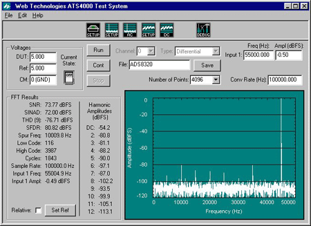
Figure 4 - Increasing the Input Frequency Worsens THD
As a sidebar, Figure 4 shows the ADC being used in an "undersampling" situation. This means that the input frequency is beyond the Nyquist rate of the converter (one-half of the conversion rate). Keep in mind that the input signal to an ADC can be any frequency, but all input frequencies will alias to a bandwidth of one-half the conversion rate. If the input signal is properly bandlimited and the ADC's sample-and-hold is good enough, the ADC can theoretically be used to digitize any frequency band.
Also, the second harmonic of the input signal would be at 110 kHz. In Figure 2, the alias of this frequency is 10 kHz. The third harmonic is at 165 kHz, which aliases to 35 kHz. If fH is the frequency of the desired harmonic, fC is the conversion rate of the ADC, and fN is the Nyquist frequency of the converter (one-half fC), then the alias frequency, fA, can be calculated from
fA = fH mod fC; if fA > fN, then fA = fC - fA ,
where fH mod fC computes the modulo (or remainder) of fH after fC has been repeatedly subtracted until fH is less than fC. For example, 10 mod 100 gives 10, while 315 mod 10 gives 15. Note that there are ways to express the computation without resorting to the if statement. However, I don't feel that they are as clear.
Finally, I should mention that ADCs can also be used in oversampling applications. Undersampling and oversampling are sometimes confused with each other. When an ADC is used for oversampling, the bandwidth of the input signal is limited to only a portion of the Nyquist bandwidth, such as one-half, one-fourth, one-tenth, etc. Usually, the data from the ADC are then processed in some manner that results in a lower data rate. For example, the processing might involve decimation using a digital low-pass filter. The end result is to either simplify the analog front-end that preceeds the ADC, or, in some cases, increase the resolution of the conversion process. (I hope to cover both undersampling and oversampling in future columns.)
Non-Windowed FFT on Non-Coherent Data
As was mentioned in Part 1 of this series,
there are a number of reasons to use coherent testing for calculating AC
results. The input signal is coherent with the conversion rate when the
data collected for the FFT contain exactly an integer number of cycles
of the input signal. If this is not the case, then something similar to
Figure
5 will result.
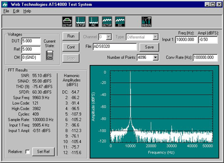
Figure 5 - Input Signal not Coherent with Conversion Rate and Non-Windowed FFT
The area underneath the fundamental is often referred to as "spectral leakage." It is as though the power in the fundamental (which should be confined to a single bin) has "leaked out" into adjacent bins.
Larger FFT Results in Lower Noise Floor
Figure 6 shows that when the number of conversions used to compute
the FFT is increased, the noise floor decreases. Compare the noise floor
of Figure 6 (an 8k point FFT) to that of Figure 2
(a 4k point FFT). The noise floor for Figure 6 is 3 dB lower,
but the SNR is the same.
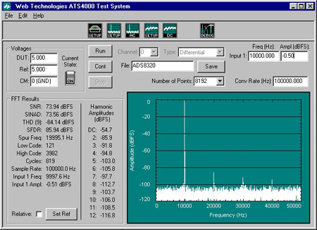
Figure 6 - Increasing the Number of Points in the FFT Lowers the Noise Floor
If you compare Figure 6 to Figure 2, you will also notice that SNR is exactly the same in both cases, while THD is slightly different (about 0.5 dB). THD is actually 0.5 dB worse in Figure 6. Since nine harmonics are being used for the THD calculation, and everything after the fourth harmonic is pretty much in the noise floor, you might expect THD to be better. However, the harmonic power is low enough that it is being affected by the random power that appears in the bins used to compute THD. Over the course of several 8k point FFTs, THD varied from 84.6 dBFS to 83.8 dBFS. The one-sigma value for the variation in THD under this particular situation is probably around 0.4 dB. Thus, the variation in THD can be attributed to test repeatability.
"Visual Cheating" with FFTs
Occasionally you will find manufacturers of ADCs displaying FFTs similar
to that of Figure 7. By placing the input signal at one-fourth
of the conversion rate, the harmonics end up near the fundamental
or either end of the FFT. This effect visually
"hides" the harmonics and makes the ADC look better. However, the
THD number still shows that there is harmonic distortion present. In this
particular display, the harmonics are actually hidden by the axes of the
graph.
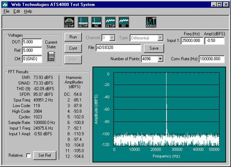
Figure 7 - Placing the Input Signal at One-Half the Conversion
Rate
to Visually Hide the Harmonics
Clipping
While it is really not of interest relative to AC results, Figure
8 shows what happens when the input of the ADC is overdriven.
When the input sine wave digitally clips at plus and minus full scale,
the resulting spectrum contains a large number of harmonics of the fundamental.
In Figure 8, these have grouped together to produce the "peaks and
valleys" look to the FFT.
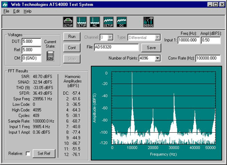
Figure 8 - Overdriving (Clipping) the ADC with a +0.5 dBFS Input Signal
Note that the input amplitude is shown to be 0.36 dBFS, while the actual input amplitude was set to 0.5 dBFS. It may seem that it would be impossible for any input signal to exceed 0 dBFS. However, the input signal is a sine wave, not a plus full-scale to minus full-scale square wave. The power in a single input frequency cannot exceed 0.707 * 0.5 * VPP, where VPP is the peak-to-peak input voltage of the ADC, without clipping the ADC (this is the definition of 0 dBFS).
If the input does clip, the power in a single bin can exceed 0 dBFS. Speaking very loosely, the Fourier transform of the input signal is a sine wave larger than 0.707 * 0.5 * VPP along with a bunch of harmonics that, when summed, clip the sine wave at the peaks, but slightly add to it elsewhere. Notice that the power of the fundamental is not 0.5 dB as expected, but shows a slight error, and is actually 0.36 dB.
As a brief comment, the total power of all the bins in the FFT can add up to 3.01 dBFS if the input signal is a square wave.
16-Bit Performance
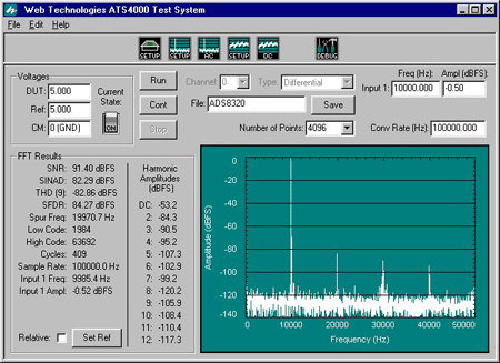
Figure 9 - 16-Bit Performance of the ADS8320
Figure 9 shows the 16-bit performance of the ADS8320. The ideal SNR for a 16-bit converter is 98.1 dB, while the ADS8320 shows about 91.4 dB of performance. This is very good compared with other 16-bit converters on the market, as most 16-bit converters show performance in the 86 dB to 92 dB range.
There is one very interesting item in regards to Figure 9. Note the grouping of harmonics near the third harmonic, and the absence of such near the second and fourth harmonics. Near the third harmonic are aliases of the seventh, thirteenth, and seventeenth harmonics as well as additional harmonics farther "out." This is a very interesting clue about the shape of the INL for this particular converter.
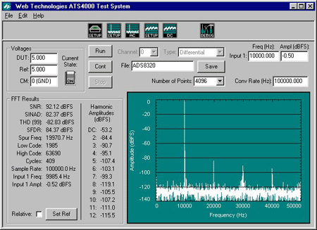
Figure 10 - 16-Bit Performance of the ADS8320
(THD calculation is for 99 harmonics)
Figure 10 shows that the SNR of the ADS8320 is actually 0.7 dB "better" than shown in Figure 9. Thus, the SNR given in Figure 9 is slightly limited by the harmonic distortion of the converter. This can be an important observation. If the INL of the converter can be made better, the SNR would improve.
Just in case you were wondering, the SNR is not being improved because 90 bins are now included in the THD calculation and are no longer included in the SNR. The SNR computation takes into account the number of bins that are used relative to the total number of bins in the FFT.
Dynamic Range
In Part 2 of this series, I mentioned that
audio
converters use different AC specifications than those used for more
general-purpose ADCs. One of those specifications is dynamic
range, which is the SNR of the converter (relative to
full scale) with a -60 dBFS input signal. While audio converters
are not generally tested with FFTs, a conceptual "audio dynamic range"
test can be performed on the ADS8320. The result is shown in Figure
11.
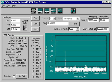
Figure 11 - The "Dynamic Range" of the ADS8320 is Given by the SNR Result
Audio ADCs are tested in a manner similar to that shown in Figure 11 because audio dynamic range is not particularly concerned with harmonic distortion. The goal is to exercise the ADC with a small-amplitude signal, but not in such a way that the sample and hold becomes a limitation (audio signals rarely come within a few dB of full scale). As can be seen in the figure, there is some small harmonic distortion, but not much (THD is -109.6 dBFS, first 9 harmonics).
Notice that the SNR of the ADC has improved from Figure 9 (a full-scale input) to Figure 11 (a -60 dBFS input) by almost 3.3 dB. The major reason for the improvement appears to be the limited SNR of the generator producing the sine wave. For the -60 dBFS test, the generator actually produces a larger signal and then attenuates it. The result is a lowering of the generator's noise floor relative to the noise floor of the ADC. To test the ADS8320 properly, the sine wave generator should possess a signal-to-noise ratio at least 10 dB better than the converter, or roughly 105 dB. This is a very difficult number to achieve, and it is unlikely that this particular generator is that good.
Some of the improvement may also be due to the local DNL in the area being tested. As can be seen in Figure 11, only 68 codes of the converter's 65,536 codes are being tested (codes 32,808 to 32,875). If the DNL is very good for those codes relative to the average DNL for all codes, then the SNR would be better.
It would seem that the ADS8320 actually has excellent SNR for a 16-bit ADC, possibly several dB better than the capability of the test setup.
Copyright ©1999-2000 ChipCenter
Part1 | Part2 | | Part4