04/14/2000
A Basic Guide to the AC Specifications of ADCs,
Part 2
By Jerry Horn
It's always good to go over the basics from time to time. In this column, I discuss the "AC" specifications associated with analog-to-digital converters (ADCs). Such specifications include signal-to-noise ratio (SNR), total harmonic distortion, signal-to-(noise plus distortion), and spurious-free dynamic range. If you need to know what the numbers mean, how to interpret them, how to measure them yourself, or are just curious about the specifications in general, read on.
This is Part 2 of a series concerning the AC Specifications of
ADCs. Part 1 looked at the basic test requirements
for measuring AC performance and defined the terms.
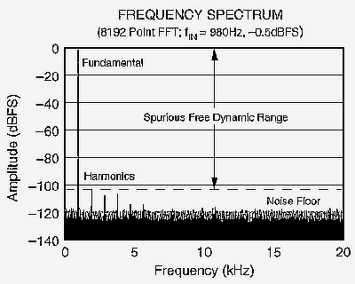
Figure 1 from Part 1 is referenced several times in the following
text, so Figure 1 has been reproduced here for reference purposes.

Figure 1 - Frequency Spectrum of a 16-bit, 40 kHz ADC Digitizing a 980 Hz Input Signal
Oddities of the FFT
There are a number of items regarding the FFT that may not be immediately
obvious and can be downright confusing when first dealing with FFTs. I
will do my best to make these as clear as possible.
The ADC's digital output represents a discrete-time system. Nothing can be known about any inputs to such a system that exceed ½ of the conversion rate of the system (called the Nyquist rate). This is why the FFT of Figure 1 is limited to a 20 kHz bandwidth (the conversion rate of the ADC is 40 kHz). What happens to the harmonics of the AC source that are greater than the Nyquist rate, do they "disappear?"

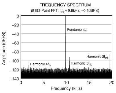
Figure 2 - Frequency Spectrum of a 16-bit, 40 kHz ADC Digitizing a 9.8 kHz Input Signal
Actually, the harmonics are still there within the frequency spectrum. This can be seen in Figure 2. However, the frequency of those harmonics beyond the Nyquist point aliases back into the frequency spectrum. Assuming a 40 kHz ADC, a harmonic at 21 kHz will alias back to 19 kHz. A harmonic whose frequency is 39 kHz aliases back to 1 kHz, while one at 41 kHz also aliases back to 1 kHz. (This aliasing somewhat complicates the code for computing the THD result.)
At this point, harmonics and aliasing can become very confusing. If a harmonic is at 41 kHz, but the alias is at 1 kHz, does the 41 kHz signal actually exist within the ADC or is it a 1 kHz signal? The best answer is that both can occur. If the sample-and-hold is the source of the distortion, then a 41 kHz tone actually is present "within" the ADC (I am somewhat oversimplifying this case). However, the converter itself only sees a 1 kHz tone because its view of the world is limited to the discrete time domain. On the other hand, if the distortion comes from the conversion process, then a "true" 41 kHz tone is not present - the 1 kHz tone is a result of the mixing between the input signal and the converter's transfer function.
The noise floor of the FFT is related to the signal-to-noise ratio of the converter. For a simple case, assume that four conversion results are taken from an ADC and processed with the FFT. The result will be two bins: the fundamental and another bin. While the other bin will also be the DC bin, let's ignore that for now. The SNR of the converter is then distributed between the fundamental bin and the second bin. So, the average noise floor that will be observed in the second bin is 3 dB lower than the converter's SNR.
Likwise, an FFT on eight conversion results will result in a noise floor that is 6 dB lower than the converter's SNR.
From this, a general equation can be defined for the noise floor of the FFT:
Noise Floor (in dBFS) = -Converter's SNR (in dB) - 3 dB * (N - 1)
where N is the log2 of the number of results in the data set (the "power" of two of the FFT). To confirm this, the first example was with four conversion results, so N equals 2 (log2 of four). The noise floor would then be the converter's SNR minus 3 dB.
Another way of looking at this is to consider the FFT itself. The FFT result is actually the output of a group of digital bandpass filters. As the data set is doubled, the width of the filter is reduced by ½, and the average noise power within that filter's bandwidth falls by 3 dB. However, the total power remains the same. I find that the most confusing aspect of the noise floor calculation is to remember to subtract one from N.
The noise floor equation is very helpful for "eyeballing" the FFT result. If you look at Figure 2, you can see that the "average" noise floor is around -123 dB. Since the spectrum is based on an 8K FFT, the noise floor is 36 dB lower than the converter's SNR, which must be -123dB + 3dB * (13 - 1), or around 87 dB. Actually, the converter's SNR is slightly better than this at around 89 dB. However, the FFT plot has been done with a fairly thick line width, and this somewhat hides the fact that the average noise floor is slightly lower than shown in Figure 2. Still, getting within 2 dB via a simple trick is not bad.
The ideal SNR of an ADC with a given J-bit resolution is defined by the equation:
Ideal SNR (in dB) = 6.02 * J + 1.76 dB
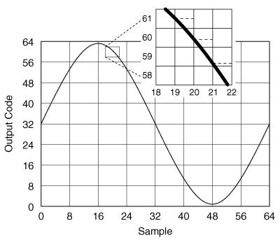
The next question is then a simple "Why?" The answer is somewhat complex, but I will try a simpler approach. Figure 3 depicts a sine input being digitized by an ideal 6-bit ADC over 32 samples. The converter holds the analog input at the start of each conversion period. The digital output is the best estimate of the analog input voltage. As shown in the enlarged section of the figure, the digital output might be in error by as much as plus or minus ½ of a least significant bit (LSB).

Figure 3 - 64 Conversions from a 6-bit ADC
The definition of SNR is signal-to-noise ratio or (signal power)/(noise power). In the case of Figure 3, the signal power [... correctly: effective value of signal ] is 0.707 * 1/2 Vpp, where Vpp is the peak-to-peak input voltage. Noise power is somewhat trickier. From the discussion so far, the noise signal that rides on top of the actual sine signal varies between ±0.5 LSB. An assumption can be made that the error is random. Thus, if the error in each digital result is graphed relative to the actual input signal, the distribution of the errors over multiple conversions is rectangular (compared to say a gaussian distribution). This means that, on average, the noise voltage is ±0.25 LSB. However, this is not the noise power. Computing the average power of a function with a rectangular probability density is not trivial for those of us who are "mathematically challenged."
Instead, I will simplify the calculation. Assume five ADC results that are in error by the following amounts: 0.05 LSB, 0.15LSB, 0.25LSB, 0.35LSB, and 0.45LSB. This is a valid assumption because the distribution is even (or rectangular). I do not need any negative numbers because the power computation will square all of them, so the sign drops out. The average power [... correctly: the effective value ] for this case is the square root of the mean of the squares:
![]() [
... that
is:
[
... that
is:![]() ]
]
So, the average noise power is 0.288 time the LSB size, where the LSB size is Vpp/2J.
Then:
If this is converted to dB ( 20 * log(result) ):
Ideal SNR (in dB) = 20*log(1.2274) + J * 20 * log(2) = 1.78 dB + J * 6.02 dB
which is pretty dang close to the actual equation (the difference is due to the simplification of the average noise power).
The ideal SNR equation raises a number of questions: "Can the SNR of an ADC be any better than the ideal?" and "How close to typical converters come to the ideal SNR?"
Actually, a low-resolution ADC (say 6 bits or less) can actually exceed the ideal SNR by a few tenths of a dB or more. The reason lies in the assumption for the ideal SNR equation: that the noise signal has a rectangular probability density. When doing AC testing, the input is a sine wave and this sine wave can be placed within the quantization levels of the ADC in such a way that the density of the error signal is not rectangular. Thus, the assumption is invalid. Unfortunately, this observation is not of much use in the real world.
Real ADCs come fairly close to matching their ideal SNR numbers within a dB or so, particularly converters with a resolution of 12 bits or less. However, when the ADC becomes very high speed, then the SNR suffers (see Practical Limits of Analog-to-Digital Conversion for more information). As a rough rule, most low-frequency 12-bit ADCs should come within 1 dB to 2 dB of their ideal number (74 dB) unless something is wrong with the converter. Higher speed 12-bit ADCs may reach only 65 dB SNR. For 16-bit converters, SNRs are generally in the 86 dB to 92 dB range.
General Observations about AC Specifications
The SNR of an ADC does not generally decrease as the frequency
of the input signal is increased. Once the ADC samples the input, the conversion
process sees only a DC signal. Since SNR is related to DNL, and DNL does
not change with input frequency, SNR does not change. However, the SNR
number calculated by the AC test setup may get worse at higher frequencies.
The usual reason for this is that high-order harmonics may increase and
some of those will be included in the SNR calculation. For most real-world
applications, you can assume that the SNR is as stated in the data sheet
without too much concern for the input frequency.
A similar statement does not apply to THD, which depends on the converter's overall INL at low input frequencies and the sample-and-hold performance at higher frequencies. The connection between INL and THD is described in The Relationship between Harmonic Distortion and Integral Non-Linearity.
The number of harmonics used for calculating THD from manufacturer to manufacturer seems to be "all over the map." In general, the number is set (somewhat arbitrarily) by the marketing department in order to show the ADC in the best light for the intended applications. If the ADC has a lot of harmonic distortion, marketing will attempt to steer the ADC towards applications where SNR is important. THD will then include a large number of harmonics so that SNR looks good. On the other hand, if harmonic distortion is important, THD will include fewer harmonics. In general, THD will include the first five to nine harmonics of the fundamental. (This can be confusing relative to the harmonic naming convention. As used here, the first five harmonics are the second (2fIN) through the sixth (6fIN).)
There is no "ideal THD" equation similar to the ideal SNR equation because the integral nonlinearity of the converter can be perfect. Thus, for very linear ADCs, the THD is set by the noise floor of the converter. Since this is related to the FFT size, THD would then be directly related to the number of conversion results used to calculate the AC performance. As a side note, this can create and has created a number of correlation issues for production testing. Here is a tip for achieving better correlation: if the absolute magnitude of a converter's THD is 10 dB better than the SNR, then repeatability will become increasing difficult as the THD value approaches the ideal noise floor of the FFT. Realize that, in this case, the THD is so good that nobody cares about correlation anyway.
The THD of a converter can improve dramatically with a modest decrease in the fundamental amplitude. For example, it may improve 6 dB with only a 2 dB reduction in input power. This fact can be used to achieve considerably better THD performance from an ADC with only a modest increase (worsening) in SNR.
SFDR is generally the difference between the fundamental power and the power in the second (2fIN) or third harmonic (3fIN) bin. Since these harmonics can decrease considerably with slightly lower input amplitude, the worst-case SFDR would seem to be defined by a full-scale input signal. This is not always true. For some converters, SFDR (relative to the converter's full scale) may suddenly increase at certain points as the input amplitude is lowered. When the input amplitude is very low, SFDR can dramatically increase because of the local INL over a small number of LSBs. Large-scale dither can sometimes be used to overcome this problem.
Audio ADCs
For years, the audio industry has created its own specifications
that are specific to the audio market. AC specifications are no exception.
Some
of the specifications are the same, others share the same name
but have different meanings, and some are completely different.
There are three key audio specifications:
| Audio
Specification |
AC Specification Definition |
| SNR | Noise power relative to FS(full scale) with the no input signal (input grounded) |
| Dynamic Range | SNR with a -60 dBFS input signal, but expressed relative to FS |
| THD+N | SINAD with a -1 dBFS to -6 dBFS input signal, but expressed relative to FS |
For most audio ADCs, SNR and Dynamic Range are equivalent. (For audio DACs, the two can differ, particularly in cases when the DAC detects that the digital input stream represents "all zeros" [called infinity zero] and physically mutes the DAC output by connecting the DAC's output to ground or to a stable reference voltage. When comparing audio DACs, read the SNR specification carefully. Some manufacturers will turn off infinity detect for the SNR test, which is a more honest measurement of SNR.)
Note the general practice within the audio community of referencing everything to full scale. This is fairly common, but not everyone does it, so read the specifications carefully.
Generally, audio ADC data sheets almost never specify THD by itself. Within audio applications, very low level harmonic distortion is considered to be inaudible. In some cases, high-level harmonic distortion can even "enhance" the sound. However, the audio community does look for reasonable (and low) THD+N numbers that come close to the SNR and Dynamic Range values. Note that, as with non-audio ADCs, some manufacturers of audio ADCs test THD+N with an input signal that is considerably below full scale (for example, -6 dBFS).
Copyright ©1999-2000 ChipCenter
Part1 | | Part3 | Part4