05/11/2000
A Basic Guide to the AC Specifications of ADCs,
Part 4
By Jerry Horn
It's always good to go over the basics from time to time. In this column, I discuss the "AC" specifications associated with analog-to-digital converters (ADCs). Such specifications include signal-to-noise ratio (SNR), total harmonic distortion, signal-to-(noise plus distortion), and spurious-free dynamic range. If you need to know what the numbers mean, how to interpret them, how to measure them yourself, or are just curious about the specifications in general, read on.
This is the final section of a four-part series concerning the AC Specifications of ADCs. Part 1 looked at the basic test requirements for measuring AC performance, Part 2 examined FFT in some detail, and Part 3 provided examples of analog-to-digital converter (ADC) operation.
In previous columns, the AC specifications associated with ADCs were examined in detail. The ADS8320, a 16-bit, 100 kHz ADC, was used to illustrate various AC specifications and issues related to these specifications (see The ADS8320: a 16-bit, 8-pin, low-power SAR ADC - Part 1 and Part 2 for more information about the ADS8320). In this column, the ADS8320 will be used to illustrate how the change in AC performance of an ADC versus various parameters can provide extremely useful information.
As a brief review, this series has focused on four AC specifications: signal-to-noise ratio (SNR), signal-to-(noise ratio plus distortion) (SINAD), total harmonic distortion (THD), and spurious-free dynamic range (SFDR). So, when referring to the "AC performance" of an ADC, the reference is to these four specifications.
Given these specifications, it is possible to graph the change in the measured results as the function of a change in an independent variable. An obvious example is to graph the change in AC performance over temperature. The resulting data can help determine the temperature range over which the ADC should be guaranteed for a given performance by the manufacturer, or the temperature range over which it can be used for a given application by the customer.
For the ADS8320, there are other not-so-obvious variables that can be changed. For example, the independent variable can be conversion rate, input amplitude, input frequency, reference voltage, supply voltage, the voltage levels on the digital inputs, and common-mode voltage. Some of these tests yield very little information, others are quite interesting. The remainder of this column will focus on the more interesting results.
AC Performance vs. Conversion Rate
This test is very simple. With an input signal whose frequency and
amplitude are fixed, vary the conversion rate of the ADC while measuring
its AC performance. As the conversion rate is increased, the sampling period
and the conversion time are both decreased. At some point, the sampling
period becomes too short, and harmonic distortion increases. At another
point, the conversion time becomes too short and the signal-to-noise ratio
begins to degrade. The results from running this test on a single ADS8320
are shown in Figure 1.
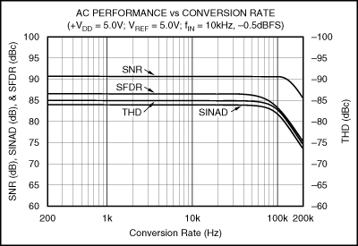
Figure 1 - AC Performance of the ADS8320 vs. Conversion Rate
From Figure 1, a number of items can be discovered. First, the harmonic distortion of the converter begins to degrade at around 50 kHz. At 100 kHz, the performance has dropped several decibels. This indicates that the sampling period for the ADS8320 is actually too short to support a good, solid 100 kHz conversion rate. It is likely that the ADS8320 suffers some integral nonlinearity (INL) degradation at 100 kHz, and that the INL of the converter can be improved by lowering the conversion rate (for more information on how THD and INL are related, see The Relationship between Harmonic Distortion and Integral Non-Linearity). (Later, it will be shown that the THD is not any better for lower input frequencies, so the problem here is not the 10 kHz frequency of the input signal.)
Also, the signal-to-noise ratio of the converter begins to degrade for conversion rates beyond 100 kHz. Since the test was done at room temperature, there is some risk that SNR may worsen at the temperature extremes when running at a 100 kHz conversion rate. So, lower conversion rates may help guarantee solid SNR performance over temperature.
It might appear that the SINAD curve shown in Figure 1 does not provide much information. However, I find SINAD very useful as a "worst-case" measurement. It defines a "first-order" boundary of the converter's worst-case performance. The area below the SINAD curve is where the ADC can be used without much concern. The converter can be used for performance "above" the SINAD curve, but only if the application is not concerned with either harmonic distortion or noise.
Likewise, it might appear that the SFDR curve does not provide useful information. Here again, I find SFDR useful, but not as useful as the SINAD curve. The SFDR curve gives a feel for the "complexity" of the harmonic distortion within the ADC. If the SFDR and THD performance are close to being the same, then the harmonic distortion is defined by a single harmonic - typically the second or third harmonic of the input signal. This is a clue to the shape of the converter's INL. If the SFDR is farther from the THD, then the harmonics of the fundamental are more similar in total power (but it cannot be determined which harmonics are present, only that the number of "significant" harmonics is greater than one).
If the SFDR and THD curves get closer and farther away as the independent variable is changed, then the converter's INL is changing and is, to some degree, dependent on the independent variable. If the two track each other, then INL is not as dependent on the independent variable. This observation proves very useful in a test discussed later.
AC Performance vs. Input Frequency
An obvious test of the converter's sample-and-hold is to graph AC performance
as a function of the frequency of the input signal. This is done in Figure
2.
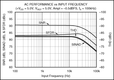
Figure 2 - AC Performance of the ADS8320 vs. Input Frequency
There are a couple of items of interest here. As has already been determined, the ADS8320 is not intended for undersampling applications (where the input signal will exceed one-half of the sample rate). The converter is good up through about 20 kHz, and then the harmonic distortion begins to worsen.
In a previous column, I made the statement that SNR rarely degrades as the input frequency is increased. In general, this is true. However, I also pointed out that higher order harmonic distortion can worsen for some converters, and that this is particularly true for the ADS8320. So, at around 20 kHz, harmonics that are not included in the THD number begin to increase, and these harmonics add to the RMS power of the "noise." So, the entire AC performance of the converter drops.
Note how the roll-off of all the curves in Figure 2 is about the same. This is a significant clue that the underlying mechanism for the decrease in performance can be traced back to the same source.
AC Performance vs. Input Frequency (with jitter on the conversion
clock)
As an interesting sidebar, Figure 3 shows the AC performance
of the ADS8320 as a function of the input frequency when there is jitter
on the conversion clock.
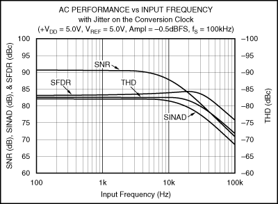
Figure 3 - AC Performance of the ADS8320 vs. Input Frequency with Clock Jitter
Notice how the presence of jitter on the conversion clock significantly affects the noise performance of the converter, but does not affect the harmonic distortion. For clock jitter whose distribution is Gaussian, the SNR of the converter falls off at a rate of 20 dB for every 10x increase in input frequency. If the clock jitter has a different distribution (rectangular, bi-modal, etc.), then the results will be different from those shown in Figure 3. As a general rule, if SNR changes at a rate different from THD as the input frequency is increased, then excessive clock jitter is strongly indicated.
AC Performance vs. Reference Voltage
Figure 4 shows the performance of the ADS8320 as the reference
voltage is varied. (The results shown in Figure 4 are not terribly
useful relative to the ADS8320, but the test can prove very helpful for
other converters.)
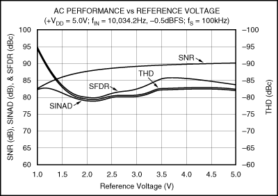
Figure 4 - AC Performance of the ADS8320 vs. Reference Voltage
As would be expected, the noise performance improves as the reference voltage is increased (the full-scale range of the converter gets larger relative to the thermal noise of the converter). Surprisingly, harmonic distortion worsens significantly at first, and then varies slightly as the reference voltage is increased.
The reason that this is surprising is that the INL of the ADS8320 is very much related to the voltage coefficient of capacitance of the ADS8320's semiconductor process. As the reference voltage is raised, the effect of this nonlinearity increases, and harmonic distortion generally degrades. However, this particular ADS8320 may have a more complex INL. When the reference voltage is around 1.0 V, the INL appears to be flat, and harmonic distortion approaches the noise floor of the FFT. When the reference voltage is raised by half a volt, the INL must change considerably. It's also possible that the voltage coefficient is more pronounced in this region and then levels off as voltage increases further.
Also, this graph shows how the SFDR curve can be useful. Note how the SFDR curve moves closer to or farther from the THD curve. This indicates that the converter's INL is changing shape as the reference voltage is varied.
AC Performance vs. Input Amplitude
Figure 5 gives the performance of the ADS8320 as the amplitude
of the input signal is increased.
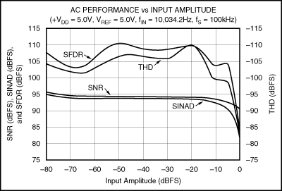
Figure 5 - AC Performance of the ADS8320 vs. Input Amplitude
As was mentioned in a previous column, it is believed that the SNR of the ADS8320 is somewhat limited at higher amplitudes (as the input signal approaches 0 dBFS) by the performance of the signal generator. So, the roll-off seen on the SNR curve over the last 10 dB may not be real.
Figure 5 can be extremely useful in certain applications, and I wish that more converter manufacturers provided this type of information. As can be seen, if the full-scale range of the signals provided to the ADS8320 were to be limited to only one-half of the converter's full-scale range, then the harmonic distortion of the converter would improve significantly. While the converter would provide only "15 bits" of useful information, the SNR performance would still be nearly 90 dB, while the THD performance would be almost -95 dB.
Considering the full-scale performance of the ADS8320 (as shown in Figure 5 by the SINAD curve), the converter gives an effective number of bits (ENOB) of approximately 13 bits. However, if the input range is limited to one-half, then ENOB jumps to 14 bits, even with the loss of one bit. (This is a little tricky, but SINAD at full-scale is 81 dBFS, while SINAD at -6 dBFS is 92 dBFS or 86 dB relative to one-half full scale. A SINAD of 81 dBFS gives an ENOB of 13 bits, while a SINAD of 86 dB gives 14 bits. So, one "real" bit was lost, but two "effective" bits were gained, resulting in a total gain of one bit.)
I should note that the results shown in Figure 5 can also be graphed using the dB and dBc results instead of the dBFS numbers. This can make it easier to visualize the performance trade-off of real bits versus effective bits. However, it makes it harder to determine SFDR over the input amplitude (which is useful information in applications involving higher speed converters used for "software radios"). I also prefer seeing the results as shown in Figure 5 because a flat line means no change in performance (and no dependence on the independent variable).
AC Performance vs. Everything
In an ideal world, ADC data sheets would provide the average, minimum,
and maximum AC performance of a large number of ADCs graphed in N dimensions,
with all possible variables included (temperature, conversion rate, input
amplitude, input frequency, common-mode voltage, reference voltage, etc.).
However, we humans have difficulty interpreting anything beyond two independent
variables, and the data would be almost impossible to assemble in a timely
manner.
Still, I hope that this column has shown the usefulness of certain AC performance graphs for both the manufacturers of ADCs as well as those that design with them. As a user of ADCs, I always want more data than is provided in the data sheet, but isn't that always the case!
Copyright ©1999-2000 ChipCenter
Part1 | Part2 | Part3