01/30/2001
DC Specifications of ADCs and
DACs
Part 4: Examples
By Jerry Horn
Sometimes a picture is worth a thousand words. I am not sure if the DC performance results included here are worth 9,000 words, but they do provide some good examples of commercial converters that are currently on the market. Collectively, they serve to provide a broad overview of the state-of-the art in converter performance as well as some good topics of discussion.
Figure 1 shows the DC performance of Microchip's MCP3208, a 12-bit, 8-channel (selectable as single-ended or pseudo differential), 100 kHz, low-power, successive-approximation register (SAR) capacitive digital-to-analog converter (CDAC) architecture analog-to-digital converter (ADC). (Whew!) This is a fairly typical ADC in the industrial converter category. The particular unit shown is a low-grade device (DNL: ±1 LSB maximum, INL: ±2 LSB maximum) that easily passes the high-grade specifications (DNL: ±1 LSB max, INL: ±1 LSB max), at least at room temperature.
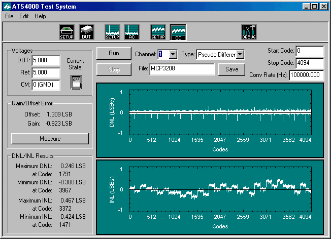
Figure 1 - Microchip's MCP3208, 12-bit, 8-channel, 100 kHz SAR CDAC ADC
It might be interesting to compare the performance of the various channels of this ADC to see how the DC performance varies from channel to channel. Actually, for this device, as for most industrial ADCs, the variation from channel to channel is well within the repeatability of the test system. In fact, the largest change I could find was 1/100 of an LSB between channel 0 and channel 1. This is not at all unusual for a well-designed converter—the front-end multiplexer should have little or no impact on DC performance. Note that this may not be true for higher speed converters or in regards to AC performance.
Figure 2 shows the DC performance of Maxim Integrated Product's MAX145, a 12-bit, single-channel (pseudo differential), 108 kHz, low-voltage, SAR ADC. This converter has very aggressive specifications for a low-voltage (2.7 V) ADC. The DNL is specified to ±0.75 LSB maximum. The INL is ±0.5 LSB maximum for the high-grade device and ±1 LSB for the low grade. The results are for a low-grade unit.
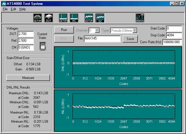
Figure 2 - Maxim's MAX145, 12-bit, 108 kHz, Low-Voltage SAR
ADC
The performance of the MAX145 raises an interesting question. Does excellent DC performance on a 12-bit converter really matter? The answer, as usual, depends on the application. The MAX145 would give very good performance for certain data acquisition tasks where it was important that each LSB represent a similar voltage input range or where AC specifications were critical (such as spurious-free dynamic range). It certainly would be suitable for any application where missing codes could not be tolerated.
On the other hand, there does not appear to be a large demand for 12-bit ADCs with excellent specifications. Very few manufacturers of ADCs offer 12-bit ADCs with INL tighter than ±1 LSB. Some do offer converters with DNL tighter than ±1 LSB (for example, ±0.75 LSB is somewhat common). The primary goal of such a specification is to reassure the user that the converter will have no missing codes. I am not aware of any converter that offers a maximum DNL or INL specification of less than ±0.5 LSB.
As a side note, I have tested 12-bit ADCs whose DNL was guaranteed to be within ±0.75 LSB only to find missing codes (which is a DNL of -1 LSB). These were later confirmed by the manufacturer. I stress that the converter in question was NOT the MAX145. I mention this only as a matter of caution, and I cannot offer any advice on how to make sure a given converter actually meets its stated specification.
Moving along, I am somewhat reluctant to offer the next result. Figure 3 shows the DC performance of Analog Device's AD7475, a 12-bit, 1 MHz, very low power (3 mW), single-channel SAR ADC. The result is within the device's preliminary specification (DNL: ±0.9 LSB max, INL: ±2 LSB max), but it may not represent the true performance of the converter. It is certainly possible that the test setup could be improved in this case as the part was "adapted" to an existing test head.
I also note that the AD7475 sample whose results are shown in Figure 3 has a date code that indicates it was manufactured in March of 1999, yet the datasheet on Analog Device's Web site is still marked preliminary.
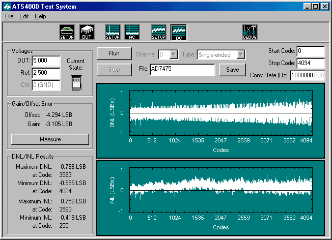
Figure 3 - Analog Device's AD7475, a 12-bit, 1 MHz, Low-Power
SAR ADC
The main reason for including this result is to show some interesting items. First, notice how the DNL and INL both increase in width for higher output codes. This generally indicates that reference noise is a problem. Higher output codes depend on the reference more than lower codes. Higher speed converters are also designed to have higher bandwidth in regards to many internal circuits. Together, these two items mean that higher output results will have more uncertainty (more transition noise). For most converters, the reference noise is smaller or much smaller than the overall DNL and INL performance of the device, which masks the noise. Not so in this case.
Another interesting item is that the DC performance of higher speed converters is simply not as good as for lower speed converters (assuming they use the same basic architecture and technology). This is a rather obvious idea, but it is often overlooked.
As a final note regarding the AD7475, I would urge anyone considering this device to ask Analog Devices for some typical performance data rather than judge it from the results shown in Figure 3. Unfortunately, the preliminary datasheet does not provide any typical DNL or INL data, making it difficult to judge the validity of the results shown.
Figure 4 shows the DC performance of Texas Instrument's ADS807 (from their Burr-Brown division). This converter is a 12-bit, 53 MHz, high-performance, pipelined ADC. If you compare Figure 4 to the earlier figures, you will detect a clear difference in the converter's DC performance. Each ADC architecture has a unique DNL and INL pattern. Within each architecture, ADCs manufactured on a similar process share certain characteristics. Thus, the DC performance of an ADC is very similar to a "fingerprint." To a trained eye, a wealth of information is revealed by the all-code DNL and INL graphs.
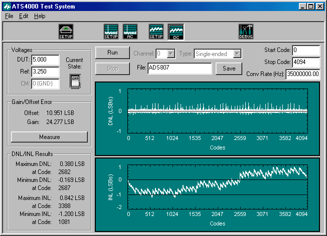
Figure 4 - Texas Instrument's ADS807, a 12-bit, 53 MHz, High-Performance
Pipelined ADC
The DC specifications for the ADS807 are ±1 LSB maximum for DNL (no missing codes guaranteed) and ±4 LSB maximum for INL. If you compare this result to the typical performance shown in the device's datasheet, you will see a few interesting differences between the DNL and INL graphs shown there and the ones shown here. Many high-speed converters are tested using a histogram method, which is a completely different method than the servo-loop technique that has been described in this series. Figure 4 is the result of a servo-loop test rather than a histogram test. Thus, there is no input frequency associated with Figure 4, and the result is the "true" DC performance of the device.
Note that the ADS807 was tested at 35 MHz, because of test limitations, instead of at the maximum 53 MHz that the converter supports. It is possible that the performance of the converter might change substantially if it is operated at a higher conversion rate. However, it is worth noting that the DC performance of most ADCs changes very little with the conversion rate (as long as it is less than or equal to the maximum recommended by the manufacturer). As a test, the ADS807 was operated at 15 MHz. There was a very slight change in performance, but nothing worth noting. For a well-designed converter, this is almost always the case.
The DC performance of Analog Device's AD7894 is shown in Figure 5. This is a 14-bit, ±10 V input, 160 kHz SAR ADC. The DNL specification is -1 LSB minimum to +1.5 LSB maximum. The INL is ±2 LSB for the low grade and ±1.5 LSB for the high grade. The device whose results are shown in Figure 5 is a low-grade device, but it easily passes high-grade specifications, at least at room temperature. For a 14-bit converter, this ADC has extremely good DNL. Note the symmetry in the INL graph about mid-scale and the "bow" seen in each half of the converter's transfer function. Again, these form a "fingerprint" unique to this converter.
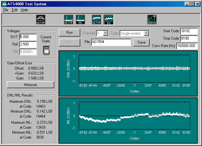
Figure 5 - Analog Device's AD7894, a 14-bit, 160 kHz, ±10
V Input, SAR ADC
As a warning to others who might use the AD7894, I note that the device I tested differed from the most recent datasheet in regards to the timing between SCLK and DOUT. The datasheet indicates that the serial output data changes just after the falling edge of SCLK, but it clearly changes just after the rising edge on my sample. It is possible that the units I have are older than the datasheet, and represent engineering or preliminary samples (they were manufactured in late 1998). On the other hand, the timing diagram shown in Figure 5 of the datasheet does not make sense in regards to the placement of the "two" leading zeros relative to the clock edges shown. I would think that the two leading zeros would span two full clock cycles, but the diagram implies that they span only 1.5 clock cycles.
Figure 6 shows the DC performance of Analog Device's AD977, a 16-bit, 100 kHz, SAR ADC. Three grades of this device are offered: grade "A" with a minimum DNL of -2 LSB and maximum DNL of +3 LSB, INL of ±3 LSB maximum; grade "B" with a minimum DNL of -1 LSB and maximum DNL of +1.75, INL of ±2 LSB maximum; and grade "C" with no minimum or maximum specifications for either DNL or INL (a "typical" value of ±2 LSB DNL and ±3 LSB INL is given). The results shown in Figure 6 are for the lowest grade device, yet it passes the high-grade specification at room temperature.
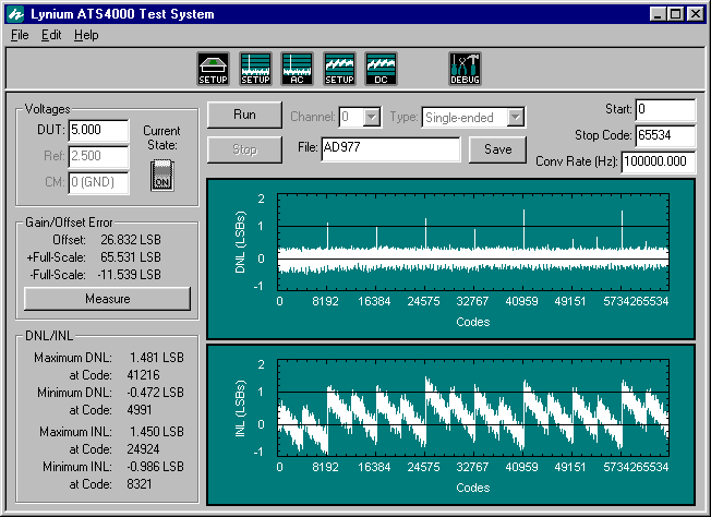
Figure 6 - Analog Device's AD977, a 16-bit, 100 kHz, SAR
ADC
It is interesting to compare Figure 6 with the DC performance of Linear Technology's LTC1595 16-bit digital-to-analog converter shown in Figure 7. All-in-all, the DC performance of most DACs is generally better than the ADCs of comparable speed and resolution. Both of these converters were designed at roughly the same time and represent state-of-the-art performance. There may be newer 16-bit ADCs on the market that have, in general, better performance than shown in Figure 6, but the AD977 is really a very good 16-bit ADC. It would be hard to imagine a 16-bit DAC with better performance than that shown in Figure 7. The LTC1595 has extremely good linearity for a 16-bit DAC, and the result shown in Figure 7 should not be taken as representative of all 16-bit DACs. (It should also be noted that the high grade of the LTC1595 is more expensive that the high grade of the AD977!)
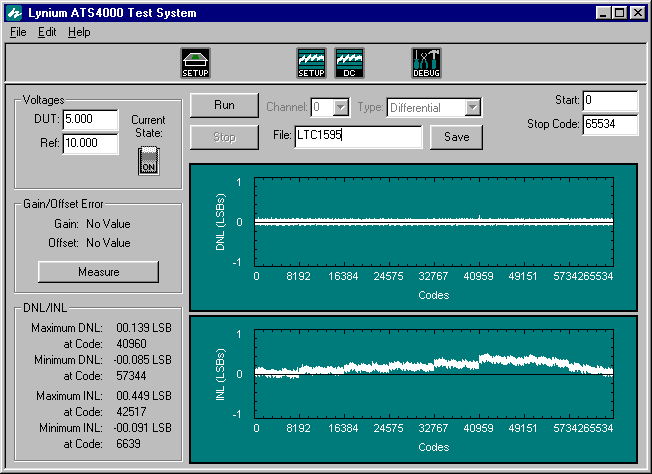
Figure 7 - Linear Technology's LTC1595, a 16-bit Industrial
DAC
There is a mistake in Figure 7. Can you spot it? If you can, you know a great deal about DC testing. The mistake does not involve the "no value" results shown in the Gain/Offset Error panel. (For these errors, "No Value" is reported because the +10 V reference could not be measured directly by the test setup.) The answer will be given at the end of this discussion.Least you think it is easy to design and manufacture a 12-bit or higher resolution converter, keep in mind that all of the results that have been presented here are for some of the best converters on the market. I also do not want you to go away thinking that all converters perform much better than their specifications would indicate.
Figure 8 shows the DC performance of a prototype 12-bit SAR ADC whose part number will not be mentioned. The target specification is ±1 LSB maximum for both DNL and INL, high grade. In this case, the prototype has a mismatched capacitor array, which is easily fixed. What is of interest here is that nearly every ADC and DAC on the market starts out by missing the target specifications. In general, "first silicon" typically works, produces "reasonable" results, but does not meet the desired performance. Over one, two, or sometimes twenty different revisions, the device gets better and better. At some point, it either meets the desired specification, the final specifications are changed to match the performance of the converter, or further work on the device is stopped.
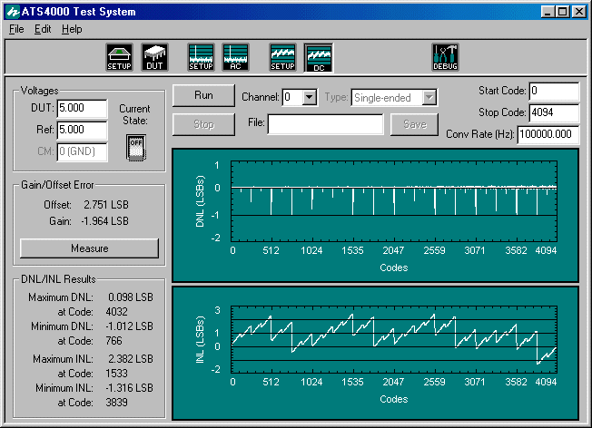
Figure 8 - A Prototype 12-bit ADC
Finally, Figure 9 shows the DC performance of an industrial 12-bit ADC. This is the low-grade version of the device, and it easily passes the maximum DNL and INL specification of ±2 LSB. It would not pass the high-grade specification of ±1 LSB. The performance of this device is not particularly good or bad—it simply illustrates that you must either purchase the grade that you require or ensure that lower grades are adequate for the task at hand. Do not assume that you can purchase low-grade units that will always pass high-grade specifications. Companies do strive to get very high yield to high grade, but grade-outs are definitely not a "marketing ploy" (well, at least not most of the time!).
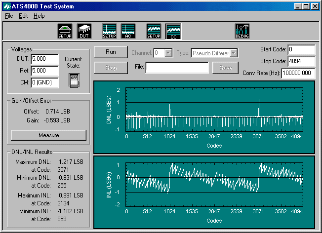
Figure 9 - A 12-bit ADC Currently on the Market
Answer to "What is wrong with Figure 7?"
For ADCs, either the first output code or the last output code cannot be tested for INL or DNL because only the transition between two codes can be found, and one of these will not have a transition point (depending on how the "transition point" is defined). For example, you can start testing at the code 0 to 1 transition, but must end at the code 2^N - 2 to 2^N - 1 transition, resulting in 2^N - 2 data points. In this example, the transition point for code M is defined as the voltage that produces code M and code M + 1 equally, meaning code 2^N - 1 has no transition point. (If the transition point is defined as the voltage that produces code M - 1 and M equally, then code 0 has no transition point. I always use M/(M + 1).)
All of this means that the "Stop Code" shown in the figures associated with ADC DC performance is always 2^N - 2. For DACs, you can test all codes (there is no "transition point"), which results in 2^N - 1 data points. So, the "Stop Code" shown in Figure 7 is incorrect. It should be 65,535 (2^N - 1), not 65,534 (2^N - 2).
If you caught this error, I am certainly impressed and my hat is off to you. You might also have too much free time on your hands!
Copyright ©1999-2000 ChipCenter